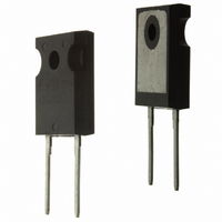
RHRG5060 Fairchild Semiconductor, RHRG5060 Datasheet - Page 2

RHRG5060
Manufacturer Part Number
RHRG5060
Description
DIODE HYPER 600V 50A TO247-2
Manufacturer
Fairchild Semiconductor
Datasheet
1.RHRG5060.pdf
(5 pages)
Specifications of RHRG5060
Voltage - Forward (vf) (max) @ If
2.1V @ 50A
Voltage - Dc Reverse (vr) (max)
600V
Current - Average Rectified (io)
50A
Current - Reverse Leakage @ Vr
250µA @ 600V
Diode Type
Standard
Speed
Fast Recovery =< 500ns, > 200mA (Io)
Reverse Recovery Time (trr)
50ns
Mounting Type
Through Hole, Radial
Package / Case
TO-247-2
Product
Ultra Fast Recovery Rectifier
Configuration
Single
Reverse Voltage
600 V
Forward Voltage Drop
2.1 V
Recovery Time
50 ns
Forward Continuous Current
50 A
Max Surge Current
500 A
Reverse Current Ir
250 uA
Power Dissipation
125 W
Mounting Style
Through Hole
Maximum Operating Temperature
+ 175 C
Minimum Operating Temperature
- 65 C
Lead Free Status / RoHS Status
Lead free / RoHS Compliant
Capacitance @ Vr, F
-
Lead Free Status / Rohs Status
Lead free / RoHS Compliant
Available stocks
Company
Part Number
Manufacturer
Quantity
Price
Company:
Part Number:
RHRG5060
Manufacturer:
FSC
Quantity:
5 000
Part Number:
RHRG5060
Manufacturer:
FAIRCHILD/仙童
Quantity:
20 000
Company:
Part Number:
RHRG5060CE4
Manufacturer:
intersil
Quantity:
1 000
©2002 Fairchild Semiconductor Corporation
Electrical Specifications
DEFINITIONS
Typical Performance Curves
R
Q
θ JC
FIGURE 1. FORWARD CURRENT vs FORWARD VOLTAGE
RR
pw = pulse width.
V
C
300
100
I
t
t
t
D = Duty cycle.
R
F
rr
10
a
b
J
1
= Instantaneous forward voltage (pw = 300 µ s, D = 2%).
= Instantaneous reverse current.
= Reverse recovery time (See Figure 9), summation of t
= Time to reach peak reverse current (See Figure 9).
= Time from peak I
= Reverse recovery charge.
= Junction Capacitance.
= Thermal resistance junction to case.
0
SYMBOL
R
Q
175
V
C
I
t
t
t
θ JC
0.5
RR
R
rr
a
b
F
J
o
C
V
100
RM
F
, FORWARD VOLTAGE (V)
1
o
C
to projected zero crossing of I
25
T
I
I
V
V
I
I
I
I
I
V
1.5
o
F
F
F
F
F
F
F
C
C
R
R
R
= 50A
= 50A, T
= 1A, dI
= 50A, dI
= 50A, dI
= 50A, dI
= 50A, dI
= 25
= 600V
= 600V, T
= 10V, I
o
C, Unless Otherwise Specified
TEST CONDITION
F
2
C
F
F
F
F
F
/dt = 100A/ µ s
/dt = 100A/ µ s
/dt = 100A/ µ s
/dt = 100A/ µ s
/dt = 100A/ µ s
= 150
= 0A
C
= 150
o
2.5
C
o
C
RM
a
based on a straight line from peak I
+ t
3
b
.
3000
1000
0.01
MIN
100
0.1
FIGURE 2. REVERSE CURRENT vs REVERSE VOLTAGE
10
-
-
-
-
-
-
-
-
-
-
-
1
0
100
TYP
140
RM
25
20
65
-
-
-
-
-
-
-
V
through 25% of I
R
200
, REVERSE VOLTAGE (V)
175
100
25
300
MAX
o
250
o
o
2.1
1.7
1.5
1.0
C
45
50
C
C
-
-
-
-
RM
(See Figure 9).
400
RHRG5060 Rev. B
UNITS
500
o
mA
C/W
µ A
nC
pF
ns
ns
ns
ns
V
V
600


