8808A 120V Fluke Electronics, 8808A 120V Datasheet
8808A 120V
Specifications of 8808A 120V


8808A 120V Summary of contents
Page 1
July 2007 © 2007 Fluke Corporation, All rights reserved. All product names are trademarks of their respective companies. ® 8808A Digital Multimeter Users Manual ...
Page 2
LIMITED WARRANTY AND LIMITATION OF LIABILITY Each Fluke product is warranted to be free from defects in material and workmanship under normal use and service. The warranty period is one year and begins on the date of shipment. Parts, product ...
Page 3
Chapter 1 Introduction and Specifications......................................................... 1-1 Introduction........................................................................................................ 1-3 Manual Set ......................................................................................................... 1-3 About this Manual ............................................................................................. 1-4 Safety Information ............................................................................................. 1-4 General Safety Summary............................................................................... 1-4 Symbols ......................................................................................................... 1-6 Options and Accessories .................................................................................... 1-7 General Specifications ....................................................................................... 1-8 Voltage .......................................................................................................... 1-8 ...
Page 4
Users Manual Storing and Shipping the Meter ......................................................................... 2-3 Power Considerations ........................................................................................ 2-3 Selecting the Line Voltage ............................................................................ 2-4 Replacing the Fuses....................................................................................... 2-4 Line-Power Fuse ....................................................................................... 2-4 Current-Input Fuses................................................................................... 2-5 Connecting to Line Power ................................................................................. 2-7 Turning Power On ...
Page 5
Introduction........................................................................................................ 4-3 Local and Remote Operations ....................................................................... 4-3 Computer Interfaces ...................................................................................... 4-3 Preparing the Meter for Operations via the RS-232 Interface ........................... 4-3 Setting Communication Parameters (RS-232) .............................................. 4-3 RS-232 Print-Only Mode .............................................................................. 4-4 Cabling the Meter to a Host ...
Page 6
8808A iv ...
Page 7
Table 1-1. Safety Information ................................................................................................. 1-5 1-2. Safety and Electrical Symbols................................................................................ 1-6 1-3. Accessories............................................................................................................. 1-7 2-1. Line Voltage to Fuse Rating................................................................................... 2-4 2-2. Line-Power Cord Types Available from Fluke...................................................... 2-7 3-1. Front-Panel Features .............................................................................................. 3-4 3-2. Display Annunciators and Indicators ...
Page 8
A-4. Typical Settling Delays (in Seconds) ..................................................................... A-6 A-5. Typical Measurement Intervals (in seconds) for Dual Display Measurements ..... A-7 vi ...
Page 9
Replacing the Line Power Fuse.............................................................................. 2-5 2-2. Replacing the Current-Input Fuses......................................................................... 2-6 2-3. Line-Power Cord Types Available from Fluke...................................................... 2-7 2-4. Bail Adjustment and Removal ............................................................................... 2-8 2-5. Boot removal.......................................................................................................... 2-9 3-1. Front Panel ............................................................................................................. 3-4 3-2. Display Annunciators ...
Page 10
8808A viii ...
Page 11
Introduction and Specifications Title Introduction........................................................................................................ 1-3 Manual Set ......................................................................................................... 1-3 About this Manual ............................................................................................. 1-4 Safety Information ............................................................................................. 1-4 General Safety Summary............................................................................... 1-4 Symbols ......................................................................................................... 1-6 Options and Accessories .................................................................................... 1-7 General Specifications ....................................................................................... 1-8 Voltage .......................................................................................................... 1-8 Dimensions .................................................................................................... ...
Page 12
Users Manual 1-2 ...
Page 13
Introduction The Fluke 8808A Digital Multimeter (hereafter referred to as the Meter 5-1/2 digit dual-display multimeter designed for bench-top, field service, and system applications. The multiple measurement functions, plus the RS-232 remote interface, make the Meter an ideal ...
Page 14
Users Manual About this Manual This manual contains all the information a new user will need to operate the Meter effectively. This manual is divided into the following chapters: Chapter 1, “Introduction and Specifications,” provides information on how safely ...
Page 15
To avoid possible electric shock, personal injury, or death, read the following before using the Meter: Use the Meter only as specified in this manual, or the protection provided by the Meter might be impaired. Do not use the Meter ...
Page 16
Users Manual Symbols Table 1-2 lists safety and electrical symbols that appear on the Meter or in this manual. Symbol Risk of danger. Important W information. See manual. Hazardous voltage. Voltage > peak ...
Page 17
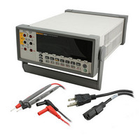
Options and Accessories Table 1-3 lists available options and accessories. Premium Test Lead Set Fuse, .25*1.25, 0.063 A, 250 V, Slow Fuse, .25*1.25, 0.125 A, 250 V, Slow F1 - Fuse 1000 V, Fast, 406INX1.5IN, BULK F2 - ...
Page 18
Users Manual General Specifications Voltage 100V Setting ...................................................... 110 V 120V Setting ..................................................... 108 V to 132 V 220V Setting ..................................................... 198 V to 242 V 240V Setting ..................................................... 216 V to 264 V Frequency.......................................................... 47 ...
Page 19
Electrical Input Protection ............................................... 1000 V all ranges Overrange .......................................................... the largest ranges of all functions except continuity and diode Remote Interfaces RS-232C Warranty One year Electrical Specifications Accuracy specifications are valid for 5-½ digit mode and ...
Page 20
Users Manual AC Voltage Specifications AC Voltage specifications are for ac sinewave signals > range. For inputs from range and <50 kHz, add an additional error of 0 range, ...
Page 21
Resistance Specifications are for 4-wire resistance function, or 2-wire resistance with REL. If REL is not used, add 0.2 Ω for 2-wire resistance plus lead resistance. Measurement Method ....................................... Current source referenced to LO input Max Lead Resistance (4-wire ohms) ...
Page 22
Users Manual Range 23 °C ± 5 °C 200 A 0.02 + 0.005 2 mA 0.015 + 0.005 20 mA 0.03 + 0.02 200 mA 0.02 + 0.005 2 A 0. 0.18 + 0.01 Notes: ...
Page 23
Frequency Gate Time .......................................................... 131 ms Measurement Method ....................................... AC-coupled input using the ac voltage measurement function. Settling Considerations ................................... When measuring frequency after a dc offset voltage change, errors Measurement Considerations ......................... To minimize measurement errors, shield inputs from ...
Page 24
Users Manual 1-14 ...
Page 25
Preparing the Meter for Operation Title Introduction........................................................................................................ 2-3 Unpacking and Inspecting the Meter ................................................................. 2-3 Contacting Fluke................................................................................................ 2-3 Storing and Shipping the Meter ......................................................................... 2-3 Power Considerations ........................................................................................ 2-3 Selecting the Line Voltage ............................................................................ 2-4 Replacing the Fuses....................................................................................... 2-4 Line-Power ...
Page 26
Users Manual 2-2 ...
Page 27
Introduction This chapter explains how to prepare the Meter for operation by selecting the proper line voltage, connecting the proper power cord for the selected line voltage, and turning the Meter on. Also included is information on the proper storage, ...
Page 28
Users Manual Selecting the Line Voltage The Meter operates on four different input line voltages. The selected line-voltage setting is visible through the window in the line-fuse holder on the Meter’s rear panel. 1. Unplug the power cord. 2. ...
Page 29
Figure 2-1. Replacing the Line Power Fuse Current-Input Fuses The 200 mA and 10 A inputs are protected by user-replaceable fuses. The 200 mA input is protected by a fuse (F2) rated at 440 mA, 1000 V (fast blow), 10,000 ...
Page 30
Users Manual 1. Remove power from the Meter by unplugging its power cord. 2. Turn the Meter upside down. 3. Remove the retaining screw on the fuse access door located on the bottom of the Meter. See Figure 2-2. ...
Page 31
Connecting to Line Power To avoid shock hazard, connect the factory supplied three- conductor line power cord to a properly grounded power outlet. Do not use a two-conductor adapter or extension cord, as this will break the protective ground connection. ...
Page 32
Users Manual Turning Power required, connect the Meter to line power. 2. Toggle the power switch on the rear panel so the “I” side of the switch is depressed. The Meter will turn on and briefly ...
Page 33
To prepare the Meter for rack mounting, remove the bail and remove the front and rear protective boots. To remove a boot, stretch a corner then slide it off as shown in Figure install the Meter into ...
Page 34
Users Manual Press Uor Vto scroll between F8808A and F45. The presently selected mode will appear bright in the display, while the other is dim. Press R to set the mode and reset the Meter. Illuminating All Display Segments ...
Page 35
Operating the Meter from the Front Panel Introduction........................................................................................................ 3-3 Dual Display ...................................................................................................... 3-6 Primary Display............................................................................................. 3-6 Secondary Display......................................................................................... 3-6 Rear Panel .......................................................................................................... 3-8 Adjusting Meter Range ...................................................................................... 3-8 Selecting a Measurement Rate........................................................................... 3-9 Selecting a Measurement Function.................................................................... 3-9 Measuring Voltage ...
Page 36
Users Manual Calibration ......................................................................................................... 3-25 3-2 ...
Page 37
Introduction The Meter can be controlled either by sending commands through its RS232 communication interface or through the front panel. This chapter explains the function and use of the controls and indicators located on the front panel of the Meter. ...
Page 38
Users Manual 1 2 INPUT V 2W/4W HI 1000 V 1000V MAX 600 V 750V 1V LO 500 V pk 200 mA MAX 10 A MAX No. A INPUT VZYR HI SENSE 4WZ HI, ...
Page 39
Table 3-1. Front-Panel Features (cont.) No. Name Operating the Meter from the Front Panel Description ...
Page 40
Users Manual Dual Display The Meter has a 5-1/2 digit vacuum fluorescent dual display. See Figure 3-2 and Table 3- 2 for an overview of the display annunciators and indicators The dual display is comprised of a primary display ...
Page 41
Table 3-2. Display Annunciators and Indicators No. Name Ext Trig REL F – MAX and MIN 2x4 Wire L mV µmA kHz ...
Page 42
Users Manual Rear Panel See Figure 3-3 and Table 3-3 for an overview of the rear-panel features No. A Line power terminal B Power switch C Fuse holder and power line voltage selector D RS-232 terminal E ...
Page 43
In autoranging mode, the Meter automatically selects the next higher range when a reading is greater than full-scale higher range is available displayed on the primary or secondary display to indicate an overload. The Meter automatically ...
Page 44
Users Manual Measuring Voltage The Meter is capable of measuring voltage up to 1000 V dc and 750 V ac. To avoid possible damage to the Meter, do not apply voltage to the Meter’s inputs until the test leads ...
Page 45
Frequency Ranging Frequency measurements are automatically ranged so that a frequency measurement is always displayed with maximum resolution. To select a range manually, press F to select the frequency function, and then press select a range ...
Page 46
Users Manual 4-Wire Resistance Measurement The Meter incorporates two methods of making a four-wire resistance measurement. The traditional method is to use four meter leads to connect the Meter to the resistance to be measured. The optional 2X4 Wire ...
Page 47
Figure 3-7. Input Connections for 4-Wire Ohms Using 2x4 Wire Leads Measuring Current To avoid blowing the current fuse or damaging the Meter, do not apply power to the circuit under test until test leads are properly installed to the ...
Page 48
Users Manual I < 200 > 200 mA and I < Automatic Input Terminal Detection For ac and dc current measurement functions, the Meter automatically detects the signal input between the ...
Page 49
Diode / Continuity Testing Press G to toggle between the continuity and diode test functions for the primary display. (These functions cannot be selected for the secondary display.) To perform a continuity test required, press G to select ...
Page 50
Users Manual Making a Triggered Measurement The Meter features a trigger function that allows you to select a measurement trigger source. When the trigger mode is set the delay between receiving the trigger and the ...
Page 51
An external TTL signal on pin 9 will trigger a measurement cycle. Alternatively, pin 9 of the RS-232 interface can be connected to pin 1 through an external switch. See Figure 3- 12. A measurement cycle is trigger when the ...
Page 52
Users Manual After a function modifier is selected, pressing any function button turns off all modifiers, causes the secondary display to go blank, and returns unmodified readings to the primary display. Relative Readings Modifier (REL) The relative readings modifier ...
Page 53
Table 3-5. dBM Reference Impedances Impedance 8000 1200 [1] 1000 900 800 600 500 [1] Voltage annunciator lit [2] Audio power readings possible To access the reference impedance list, press Q then press W. The reference impedance currently selected is ...
Page 54
Users Manual Level 1 (0. reading) Level 2 (0 reading) Level reading) Level 4 ( reading) To change the response level, press Q and I. The response level currently ...
Page 55
Using the Function Modifiers in Combination You can use multiple function modifiers simultaneously. Selected modifiers are evaluated in the following order: Touch Hold, minimum/maximum, and then relative readings. The Meter first looks for a stable measurement for Touch Hold, then ...
Page 56
Users Manual Buttons Q V [1] and Q U [1] and [1] Hold both buttons for 2 seconds. Compare Function (COMP) The Meter has a compare function (COMP) that provides an easy way to determine if a reading falls ...
Page 57
Using the List Editor The list editor is used to select the options described in Table 3-7. You may abort an edit and return to normal operation at any time by pressing Q. To use the list editor: 1. Select ...
Page 58
Users Manual Using the Number Editor Use the number editor to edit the relative base for the relative readings modifier and to set the high and low threshold values for the compare function. Note that you can abort the ...
Page 59
Measurement function on secondary display Range mode on primary display (manual or autorange) Measurement rate (slow, medium, fast) Dual display status (active or inactive) Any combination of selected function modifiers Touch Hold level ( Last recorded minimum ...
Page 60
Users Manual 3-26 ...
Page 61
Operating the Meter Using the Computer Introduction........................................................................................................ 4-3 Local and Remote Operations ....................................................................... 4-3 Computer Interfaces ...................................................................................... 4-3 Preparing the Meter for Operations via the RS-232 Interface ........................... 4-3 Setting Communication Parameters (RS-232) .............................................. 4-3 RS-232 Print-Only Mode .............................................................................. 4-4 ...
Page 62
Users Manual Compare Commands and Queries ................................................................. 4-24 Trigger Configuration Commands................................................................. 4-24 Miscellaneous Commands and Queries......................................................... 4-25 RS-232 Remote / Local Configurations ........................................................ 4-25 RS-232 Save / Recall System Configurations ............................................... 4-26 Sample Program Using the RS-232 Computer Interface ...
Page 63
Introduction This chapter describes how to set up, configure and operate the Meter via the RS-232 computer interface on the Meter’s rear panel. The Meter can be operated from a host (a terminal, controller, PC, or computer) by sending commands ...
Page 64
Users Manual 6. Press R to review the settings. When you are ready to accept the settings, press and hold R. Table 4-1. RS-232 Communication Parameters Factory Settings Parameter Interface Baud rate Parity Number of data bits Number of ...
Page 65
Table 4-2. Print Rates in RS-232 Print-Only Mode Seconds between Outputs Rate (N) Slow Medium Fast 1 0.4 0.05 0.01 2 0.8 0.1 0.02 5 2.0 0.25 0.05 10 4.0 0.5 0.1 20 8.0 1.0 0.2 50 20.0 2.5 0.5 ...
Page 66
Users Manual Character Echoing and Deletion When the Meter is operated via the RS-232 interface, you can control whether characters are echoed to the host's display screen. When Echo is on, characters sent to the Meter are echoed on ...
Page 67
If the Meter does not respond as indicated, refer to the “If Test Fails” section. If Test Fails If the Meter does not respond as indicated in the “Installation Test for RS-232 Operation” section, perform the following: 1. Ensure ...
Page 68
Users Manual In some instances, a terminator is automatically transmitted at the end of the host’s output string (the Meter's input string). Sending Numeric Values to the Meter Numeric values can be sent to the Meter as integers, real ...
Page 69
OHM(format 2) +/- 1.0E+9 Triggering Output The Meter takes measurements when triggered to do so. There are five trigger types, which are described in Table 4-3. Triggers fall into two basic categories: Internal trigger, which triggers measurements ...
Page 70
Users Manual If you enter the remote mode with trigger type selected, the Meter remains in its external trigger state; however, because the Meter is in the remote mode, you will only be able to trigger ...
Page 71
Status Registers The contents of the status register (STB) are determined by the service enable register (SRE), event status register (ESR), event status enable register (ESE), and the output buffer. These status registers are explained in the following paragraphs and ...
Page 72
Users Manual 6 7 & & Service Request Generation Event Status and Event Status Enable Registers The ESR assigns specified events to specific bits. (See Figure 4-3 and Table 4-6.) When a bit in the ESR is ...
Page 73
The ESE is a mask register that allows the host to enable or disable (mask) each bit in the ESR. When a bit in the ESE is set to 1, the corresponding bit in the ESR is enabled. When any ...
Page 74
Users Manual Bit No. 0 Operation Complete (OPC) 1 Not used 2 Query Error (QYE) 3 Device-Dependent Error (DDE) 4 Execution Error (EXE) 5 Command Error (CME) 6 Not used 7 Power On Status Byte Register The STB is ...
Page 75
Table 4-7. Description of Bits in the Status Byte Register (STB) (cont.) Bit No. Name 6 Master Summary Status (MSS) 7 Not used [1] As read by *STB? Command. If the STB is read by a serial poll, bit 6 ...
Page 76
Users Manual Common Commands Table 4-8 describes common commands. Command *CLS Clear Status *ESE <value> Event Status Enable *ESE? Event Status Enable Query *ESR? Event Status Register Query *IDN? Identification Query *OPC Operation Complete Command *OPC? Operation Complete Query ...
Page 77
Table 4-8. Common Commands (cont.) Command Name *SRE Service Request Enable *SRE? Service Request Enable Query *STB? Read Status Byte *TRG Trigger *TST Self test query *WAI Wait-to-Continue Function Commands and Queries Table 4-9 describes function commands and queries. Refer ...
Page 78
Users Manual Commands Primary Display FUNC1? (Not applicable) OHMS WIRE2, WIRE4 VAC [1] VACDC VDC [1] When AACDC or VACDC is selected, no function can be selected for the secondary display. An execution error is generated if attempted. 4-18 ...
Page 79
Function Modifier Commands and Queries Table 4-10 describes function modifier commands and queries. A function modifier causes the Meter to modify the normal operation of a measurement function or to perform an action on a measurement before displaying a reading. ...
Page 80
Users Manual Table 4-10. Function Modifier Commands and Queries (cont.) Command HOLDTHRESH? MAX MAXSET <numeric value> Meter enters MAX modifier with <numeric value> as the maximum value. MIN MINSET <numeric value> MNMX MNMXSET <numeric1, numeric2> MMCLR 4-20 Description Meter ...
Page 81
Table 4-10. Function Modifier Commands and Queries (cont.) Command MOD? Meter returns a numeric value indicating modifiers in use, where 1 = MIN MAX HOLD dB Power REL; and ...
Page 82
Users Manual Table 4-11. Range and Measurement Rate Commands and Queries (cont.) Command RANGE <value range> RANGE1? RANGE2? RATE <speed> RATE? 4-22 Description Sets the primary display to <value range> where <value range> is the number in the Range ...
Page 83
Measurement Queries Table 4-12 describes measurement queries, which are shown on the primary and/or secondary displays. Table 4-12. Measurement Queries Command MEAS1? Meter returns the value shown on the primary display after the next triggered measurement is completed. MEAS2? Meter ...
Page 84
Users Manual Compare Commands and Queries Table 4-13 describes the compare commands and queries. These commands cause the Meter to determine whether a measurement is higher than, lower than, or within a specified range. These commands correspond with C, ...
Page 85
Miscellaneous Commands and Queries Table 4-15 describes miscellaneous commands and queries. Table 4-15. Miscellaneous Commands and Queries Command ^C (CONTRL C) Causes =><CR><LF> output. FORMAT <format> Set output <format> Format 1 outputs measurement values ...
Page 86
Users Manual Command REMS RWLS LOCS LWLS RS-232 Save / Recall System Configurations Table 4-18 describes RS-232 save/recall system configuration commands, which are used with the RS-232 interface to set up the remote/local configuration of the Meter. Command Save ...
Page 87
Sample Program Using the RS-232 Computer Interface Figure 4 annotated BASIC A program written for a PC that demonstrates how the Meter can be used with the RS-232 computer interface. Figure 4-4. Sample Program for RS-232 Computer Interface ...
Page 88
Users Manual 4-28 ...
Page 89
Appendix A Applications ........................................................................................................ A-1 B 2X4 Test Leads ................................................................................................... B-1 Appendices Title Page ...
Page 90
Users Manual ...
Page 91
Introduction This chapter discusses some applications that will help you use the Meter effectively. These applications assume you are familiar with the basic operation of the Meter and have a basic understanding of electronics. A sophisticated understanding of electrical circuits ...
Page 92
Users Manual Figure A-1. Example of Dual Display Showing Volts AC and Frequency Using Measurement Functions in Combination The dual display allows you to display select combinations of measurements for the input signal being measured. Allowable combinations of properties ...
Page 93
If the relative readings value voltage measurement is shown in the primary display and the dc voltage itself is shown in the secondary display, the Meter takes a single measurement and updates both displays with it. Updating ...
Page 94
Users Manual Primary Secondary Display REL Resistance HOLD Actual Value Figure A-2. DC Voltage and DC Current Measurement on Input Signal The lead from the internal measuring circuitry of the meter to the LO terminal (on the front panel) ...
Page 95
Repsonse Times Response time is the time between a change in an input and when that change is displayed. The meter’s response time depends on many factors: the measurement function selected, number of measurements being made (single measurement when only ...
Page 96
Users Manual Table A-3. Typical Single Measurement Response Times (in Seconds) Meas. Auto Function Range D 1.2 A 1.2 E 1.4 B 1.0 O 1.6 G N/A F 1.0 [1] Time to autorange a new measurement from the lowest ...
Page 97
Table A-5. Typical Measurement Intervals (in Seconds) for Dual Display Measurements Meas. Range Function D All A All E All B All O N/A G N/A F N/A External Trigger The external trigger can be used with or without settling ...
Page 98
... For example, determining the leakage current of a battery operated device in its standby mode is critical in determining the time before battery re- charge is needed. Traditional multimeters make these measurements using a shunt method shown in Figure A-3. The shunt resistor converts the current to be measured to a voltage, which is called the burden voltage ...
Page 99
Introduction The optional Fluke TL2X4W test leads simplify making 4-wire ohms measurements by integrating the Hi-Hi Sense and Lo-Lo Sense test leads into one cable. The Meter’s Input HI and LO jacks consist of two contacts. One contact is connected ...
Page 100
Users Manual B-2 ...