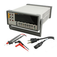
8808A 120V Fluke Electronics, 8808A 120V Datasheet

8808A 120V
Specifications of 8808A 120V
8808A 120V Summary of contents
Page 1
PN 2716412 July 2007 © 2007 Fluke Corporation, All rights reserved. Printed in China All product names are trademarks of their respective companies. 8808A Digital Multimeter Getting Started Manual Specifications ® ...
Page 2
LIMITED WARRANTY AND LIMITATION OF LIABILITY Each Fluke product is warranted to be free from defects in material and workmanship under normal use and service. The warranty period is one year and begins on the date of shipment. Parts, product ...
Page 3
Title Introduction........................................................................................................ 1 Manual Set ......................................................................................................... 2 Contacting Fluke................................................................................................ 2 Safety Information ............................................................................................. 2 General Safety Summary............................................................................... 2 Symbols ......................................................................................................... 4 Unpacking and Inspecting the Meter ................................................................. 4 Storing and Shipping the Meter ......................................................................... 4 Power Considerations ........................................................................................ 5 Selecting ...
Page 4
...
Page 5
Table 1. Safety Information ................................................................................................. 3 2. Safety and Electrical Symbols................................................................................ 4 3. Line Voltage to Fuse Rating................................................................................... 6 4. Line-Power Cord Types Available from Fluke...................................................... 8 5. Factory Settings of RS-232 Communication Parameters....................................... 11 6. Accessories............................................................................................................. 11 Figure 1. ...
Page 6
Getting Started Manual iv ...
Page 7
Introduction The Fluke 8808A Digital Multimeter (hereafter referred to as the Meter 5-1/2 digit dual-display multimeter designed for bench-top, field service, and system applications. The multiple measurement functions, plus the RS-232 remote interface, make the Meter an ideal ...
Page 8
Getting Started Manual Manual Set The manual set for this Meter consists of a printed Getting Started Manual and a Users Manual on a CD-ROM. This manual contains basic getting started information, contacting Fluke, unpacking, and general specifications. This ...
Page 9
To avoid possible electric shock, personal injury, or death, read the following before using the Meter: Use the Meter only as specified in this manual, or the protection provided by the Meter might be impaired. Do not use the Meter ...
Page 10
Getting Started Manual Symbols Table 2 lists safety and electrical symbols that appear on the Meter or in this manual. Symbol Risk of danger. Important W information. See manual. Hazardous voltage. Voltage > ...
Page 11
To store the Meter, place the box under cover in a location that complies with the storage environment specifications described in the “General Specifications” section later in this manual. Power Considerations The Meter operates on varying power distribution standards found ...
Page 12
Getting Started Manual Line Voltage Selection 100 / 120 220 / 240 Current-Input Fuses The 200 mA and 10 A inputs are protected by user-replaceable fuses. The 200 mA input is protected by a fuse rated at 440 mA, ...
Page 13
XW Warning To avoid electric shock, remove the power cord and any test leads from the Meter before opening the current-input fuse access door. To replace the current-input fuses: 1. Unplug the power cord. 2. Turn the Meter upside down. ...
Page 14
Getting Started Manual Connecting to Line Power To avoid shock hazard, connect the factory supplied three- conductor line power cord to a properly grounded power outlet. Do not use a two-conductor adapter or extension cord, as this will break ...
Page 15
Turning Power required, connect the Meter to line power. 2. Toggle the power switch on the rear panel so the “I” side of the switch is depressed. The Meter will turn on and briefly illuminate all LCD ...
Page 16
Getting Started Manual To install the Meter into the rack, refer to the instructions provided with the Rack Mount Kit. Preparing the Meter for Operations via the RS-232 Interface The RS-232 interface allows ASCII asynchronous serial communication between the ...
Page 17
Press scroll to desired data bits ( selection, then press R for 2 seconds to set parity. Echo appears on the secondary display, and 0n or 0FF appears on the primary display. 5. ...
Page 18
Getting Started Manual Cleaning the Meter To avoid electric shock or damage to the Meter, never get water inside the Meter. To avoid damaging the Meter’s housing, do not apply solvents to the Meter. If the Meter requires cleaning, ...
Page 19
PN 2716412 July 2007 © 2007 Fluke Corporation, All rights reserved. Printed in China All product names are trademarks of their respective companies. 8808A Digital Multimeter Specifications ® ...
Page 20
...
Page 21
Title General Specifications ....................................................................................... 1 Voltage .......................................................................................................... 1 Dimensions .................................................................................................... 1 Display........................................................................................................... 1 Environment .................................................................................................. 1 Safety............................................................................................................. 2 EMC .............................................................................................................. 2 Triggering ...................................................................................................... 2 Math Functions.............................................................................................. 2 Electrical........................................................................................................ 2 Remote Interfaces .......................................................................................... 2 Warranty ........................................................................................................ 2 Electrical Specifications .................................................................................... 2 ...
Page 22
Getting Started Manual 2 ...
Page 23
General Specifications Voltage 100V Setting ...................................................... 110 V 120V Setting ..................................................... 108 V to 132 V 220V Setting ..................................................... 198 V to 242 V 240V Setting ..................................................... 216 V to 264 V Frequency.......................................................... 440 ...
Page 24
Getting Started Manual Safety Complies with IEC 61010-1:2001, ANSI/ISA 61010-1 (S82.02.01):2004, UL 61010-1:2004, CAN/CSA C22.2 No. 61010.1:2004, CAT I 1000V/CAT II 600 V. EMC Designed to comply with IEC 61326-1:1997+A1:1998+A2:2000 Triggering Trigger Delay .................................................... 400 ms External Trigger Delay ...
Page 25
Range 90 days 23 °C ± 5 °C 200 mV 0.01 + 0.003 2 V 0.01 + 0.002 20 V 0.01 + 0.003 200 V 0.01 + 0.002 1000 V 0.01 + 0.002 Notes: [1] Accuracy given as ± (% ...
Page 26
Getting Started Manual Range Frequency 200 – 45Hz 45 Hz – 20 kHz 20 kHz – 50 kHz 50 kHz – 100 kHz 750 – 45Hz 45 Hz – 20 kHz 20 kHz ...
Page 27
DC Current Input Protection ............................................... Tool accessible 1000 V and 440 mA / 1000 V fuses. Shunt Resistance.............................................. 0.01 Ω for 2 A and 10 A ranges Full-Scale Range (5-1/2 Digits) Slow 200 uA 199.999 µA 0.001 ...
Page 28
Getting Started Manual Range Frequency 45Hz kHz 200 45Hz kHz 45Hz kHz 10 ...


