ADNS-2610 Avago Technologies US Inc., ADNS-2610 Datasheet - Page 4
ADNS-2610
Manufacturer Part Number
ADNS-2610
Description
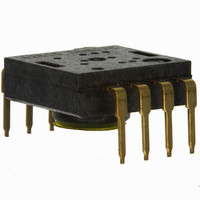
SENSOR OPTICAL MOUSE 8-DIP
Manufacturer
Avago Technologies US Inc.
Datasheet
1.ADNK-2610.pdf
(27 pages)
Specifications of ADNS-2610
Lead Free Status / RoHS Status
Lead free / RoHS Compliant
Lead Free Status / RoHS Status
Lead free / RoHS Compliant, Lead free / RoHS Compliant
Other names
516-1843
ADNS-2610
ADNS-2610


PCB Assembly Considerations
1. Insert the sensor and all other electrical components
2. Bend the LED leads 90° and then insert the LED into
3. Insert the LED/clip assembly into PCB.
4. Wave solder the entire assembly in a no-wash solder
5. Place the lens onto the base plate.
6. Remove the protective kapton tape from optical aper-
7. Insert PCB assembly over the lens onto the base plate
8. The optical position reference for the PCB is set by the
9. Install mouse top case. There MUST be a feature in
4
into PCB. Note: Pin 1 of the sensor should always be
the reference point of mechanical cutouts.
the assembly clip until the snap feature locks the LED
base.
process utilizing solder fixture. The solder fixture is
needed to protect the sensor during the solder process.
The fixture should be designed to expose the sensor
leads to solder while shielding the optical aperture
from direct solder contact. The solder fixture is also
used to set the reference height of the sensor to the
PCB top during wave soldering (Note: DO NOT remove
the kapton tape during wave soldering).
ture of the sensor. Care must be taken to keep contami-
nants from entering the aperture. It is recommended
not to place the PCB facing up during the entire mouse
assembly process. The PCB should be held vertically for
the kapton removal process.
aligning post to retain PCB assembly. The sensor ap-
erture ring should self-align to the lens.
base plate and lens. Note that the PCB motion due to
button presses must be minimized to maintain optical
alignment.
the top case to press down onto the clip to ensure
all components are interlocked to the correct vertical
height.
Surface
Figure 7. Sectional view of PCB assembly highlighting optical mouse components (optical mouse sensor, clip, lens,
LED, PCB and base plate).
Base Plate
Lens/Light Pipe
PCB
SERIAL
Figure 6. Block diagram of ADNS-2610 optical mouse sensor.
Design Considerations for Improving ESD Performance
The flange on the lens has been designed to increase
the creepage and clearance distance for electrostatic
discharge. The table below shows typical values assuming
base plate construction per the Avago supplied IGES file
and HDNS-2100 lens flange.
Typical Distance
Creepage
Clearance
For improved ESD performance, the lens flange can be
sealed (i.e. glued) to the base plate. Note that the lens
material is polycarbonate and therefore, cyanoacrylate
based adhesives or other adhesives that may damage the
lens should NOT be used.
PORT
CONTROL
LED
SDIO
SCK
Sensor
SERIAL
PROCESSOR
PORT
CONTROL
IMAGE
LED
Millimeters
16.0
2.1
OSCILLATOR
Clip
REFA
V
GND
DD
OSC_OUT
OSC_IN
VOLTAGE
REFERENCE
5 VOLT
POWER
RESONATOR
LED
Related parts for ADNS-2610
Image
Part Number
Description
Manufacturer
Datasheet
Request
R

Part Number:
Description:
Optical Mouse Sensor,DIP
Manufacturer:
Avago Technologies US Inc.
Datasheet:

Part Number:
Description:
Optical Mouse Sensor,DIP
Manufacturer:
Avago Technologies US Inc.
Datasheet:

Part Number:
Description:
Trim Lens For ADNS-3530
Manufacturer:
Avago Technologies US Inc.
Datasheet:

Part Number:
Description:
8 DIP SFF Navigation Sensor
Manufacturer:
Avago Technologies US Inc.
Datasheet:

Part Number:
Description:
Trim Lens For ADNS-5090
Manufacturer:
Avago Technologies US Inc.
Datasheet:

Part Number:
Description:
BLACK CLIP FOR ADNS-5000
Manufacturer:
Avago Technologies US Inc.
Datasheet:
Part Number:
Description:
Lens For ADNS-7630
Manufacturer:
Avago Technologies US Inc.
Datasheet:

Part Number:
Description:
Optical Mouse Sensor,DIP
Manufacturer:
Avago Technologies US Inc.
Datasheet:
Part Number:
Description:
Optical Mouse Sensor,DIP
Manufacturer:
Avago Technologies US Inc.
Datasheet:
Part Number:
Description:
Low Power Wireless LED Sensor
Manufacturer:
Avago Technologies US Inc.
Datasheet:

Part Number:
Description:
OPTOCOUPLER GATE DRV 2A 16-SOIC
Manufacturer:
Avago Technologies US Inc.
Datasheet:
Part Number:
Description:
OPTOCOUPLER 2CH 2.5A 16-SOIC
Manufacturer:
Avago Technologies US Inc.
Datasheet:

Part Number:
Description:
OPTOCOUPLER GATE DRV 0.4A 16SOIC
Manufacturer:
Avago Technologies US Inc.
Datasheet:

Part Number:
Description:
OPTOCOUPLER 2.0A 250KHZ 8-DIP
Manufacturer:
Avago Technologies US Inc.
Datasheet:

Part Number:
Description:
OPTOCOUPLER 2.0A 250KHZ GW 8-SMD
Manufacturer:
Avago Technologies US Inc.
Datasheet: