AD9788-EBZ Analog Devices Inc, AD9788-EBZ Datasheet - Page 26
AD9788-EBZ
Manufacturer Part Number
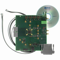
AD9788-EBZ
Description
BOARD EVAL FOR AD9788
Manufacturer
Analog Devices Inc
Series
TxDAC®r
Datasheet
1.AD9785BSVZ.pdf
(64 pages)
Specifications of AD9788-EBZ
Design Resources
Powering the AD9788 Using ADP2105 for Increased Efficiency (CN0141)
Number Of Dac's
2
Number Of Bits
16
Outputs And Type
2, Differential
Sampling Rate (per Second)
800M
Data Interface
Serial
Settling Time
22ms
Dac Type
Current
Voltage Supply Source
Analog and Digital
Operating Temperature
-40°C ~ 85°C
Utilized Ic / Part
AD9788
Silicon Manufacturer
Analog Devices
Application Sub Type
DAC
Kit Application Type
Data Converter
Silicon Core Number
AD9788
Kit Contents
Board
Development Tool Type
Hardware - Eval/Demo Board
Lead Free Status / RoHS Status
Lead free / RoHS Compliant


AD9785/AD9787/AD9788
The digital control (DCTL) register comprises two bytes located at Address 0x01.
Table 11. Digital Control (DCTL) Register
Address
0x01
Bit
[15]
[14]
[13]
[12]
[11]
[10]
[9]
[8]
[7:6]
[5]
[4]
[3]
[2]
[1]
[0]
Name
Reserved
Clear phase
accumulator
PN code sync
enable
Sync mode select
Pulse sync enable
Reserved
Inverse sinc
enable
DATACLK
output enable
Interpolation
Factor [1:0]
Data format
Single-port mode
Real mode
IQ select invert
Q first (data
pairing)
Modulator gain
control
Description
Reserved for future use.
0: Default. The feature that clears the NCO phase accumulator is inactive. The phase
accumulator operates as normal.
1: The NCO phase accumulator is held in the reset state until this bit is cleared.
0: PN code synchronization mode is disabled.
1: PN code synchronization mode is enabled. See the Device Synchronization section for
details.
0: Selects pulse mode synchronization.
1: Selects PN code synchronization. See the Device Synchronization section for details.
0: Pulse mode synchronization is disabled.
1: Pulse mode synchronization is enabled. See the Device Synchronization section for details.
Reserved for future use.
0: Default. The inverse sinc filter is bypassed.
1: The inverse sinc filter is enabled and operational.
0: Data clock pin is disabled.
1: Default. The output data clock pin is active (configured as an output).
Specifies the filter interpolation rate where:
0: Default. The incoming data is expected to be twos complement.
1: The incoming data is expected to be offset binary.
0: Default. When the single-port bit is cleared, I/Q data is sampled simultaneously on the P1D
and P2D input ports. Specifically, I data is registered from the P1D[15:0] pins and Q data is
registered from the P2D[15:0] pins.
1: When the single-port bit is set, I/Q data is sampled in a serial word fashion on the P1D input
port. In this mode, the I/Q data is sampled into the part at twice the I/Q sample rate.
0: Default. Logic 0 is the inactive state for this bit.
1: When the real mode bit is set, the Q path logic after modulation and phase compensation is
disabled.
0: Default. When the IQ Select Invert bit is cleared, a Logic 1 on the TXENABLE pin indicates
I data, and a Logic 0 on the TXENABLE pin indicates Q data, if the user is employing a
continuous timing style on the TXENABLE pin.
1: When the IQ Select Invert bit is set, a Logic 1 on the TXENABLE pin indicates Q data, and a
Logic 0 on the TXENABLE pin indicates I data, if the user is employing a continuous timing
style on the TXENABLE pin.
0: Default. When the Q first bit is cleared, the I/Q data pairing is nominal, that is, the I data
precedes the Q data in the assembly of the I/Q data pair. As such, data input to the device as
I0, Q0, I1, Q1 . . . In, Qn is paired as follows: (I0/Q0), (I1/Q1) … (In/Qn).
1: When the Q first bit is set, the I/Q data pairing is altered such that the I data is paired with
the previous Q data. As such, data input to the device as I0, Q0, I1, Q1, I2, Q2, I3, Q3 . . . In, Qn is
paired as follows: (I1/Q0), (I2/Q1), (I3/Q2) … (In + 1/Qn).
0: Default. No gain scaling is applied to the NCO input to the internal digital modulator.
1: Gain scaling of 0.5 is applied to the NCO input to the modulator. This can eliminate
saturation of the modulator output for some combinations of data inputs and NCO signals.
00: 1× interpolation
01: 2× interpolation
10: 4× interpolation
11: 8× interpolation
Rev. A | Page 26 of 64
Related parts for AD9788-EBZ
Image
Part Number
Description
Manufacturer
Datasheet
Request
R

Part Number:
Description:
Dual 16B, 1.0 GSPS TxDAC
Manufacturer:
Analog Devices Inc
Datasheet:

Part Number:
Description:
±1.7g Dual-Axis IMEMS Accelerometer Evaluation Board
Manufacturer:
Analog Devices Inc
Datasheet:
Part Number:
Description:
Inertial Sensor Evaluation System
Manufacturer:
Analog Devices Inc
Datasheet:
Part Number:
Description:
Manufacturer:
Analog Devices Inc
Datasheet:
Part Number:
Description:
Manufacturer:
Analog Devices Inc
Datasheet:
Part Number:
Description:
Manufacturer:
Analog Devices Inc
Datasheet:
Part Number:
Description:
Manufacturer:
Analog Devices Inc
Datasheet:
Part Number:
Description:
Manufacturer:
Analog Devices Inc
Datasheet:
Part Number:
Description:
Manufacturer:
Analog Devices Inc
Datasheet:
Part Number:
Description:
Manufacturer:
Analog Devices Inc
Datasheet:
Part Number:
Description:
Manufacturer:
Analog Devices Inc
Datasheet:
Part Number:
Description:
Manufacturer:
Analog Devices Inc
Datasheet:
Part Number:
Description:
Manufacturer:
Analog Devices Inc
Datasheet: