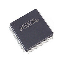
EPM1270GT144I5N Altera, EPM1270GT144I5N Datasheet - Page 52

EPM1270GT144I5N
Manufacturer Part Number
EPM1270GT144I5N
Description
MAX II
Manufacturer
Altera
Datasheet
1.EPM1270GT144I5N.pdf
(88 pages)
Specifications of EPM1270GT144I5N
Family Name
MAX II
Memory Type
Flash
# Macrocells
980
Frequency (max)
1.8797GHz
Propagation Delay Time
10ns
Number Of Logic Blocks/elements
127
# I/os (max)
116
Operating Supply Voltage (typ)
1.8V
In System Programmable
Yes
Operating Supply Voltage (min)
1.71V
Operating Supply Voltage (max)
1.89V
Operating Temp Range
-40C to 100C
Operating Temperature Classification
Industrial
Mounting
Surface Mount
Pin Count
144
Package Type
TQFP
Lead Free Status / Rohs Status
Compliant
Available stocks
Company
Part Number
Manufacturer
Quantity
Price
Company:
Part Number:
EPM1270GT144I5N
Manufacturer:
ALTERA
Quantity:
612
4–2
I/O Pins Remain Tri-Stated during Power-Up
Signal Pins Do Not Drive the V
AC and DC Specifications
Hot Socketing Feature Implementation in MAX II Devices
MAX II Device Handbook
1
A device that does not support hot-socketing may interrupt system operation or cause
contention by driving out before or during power-up. In a hot socketing situation, the
MAX II device’s output buffers are turned off during system power-up. MAX II
devices do not drive out until the device attains proper operating conditions and is
fully configured. Refer to
about turn-on voltages.
MAX II devices do not have a current path from I/O pins or GCLK[3..0] pins to the
V
(or removed from) a system board that was powered up without damaging or
interfering with system-board operation. When hot socketing, MAX II devices may
have a minimal effect on the signal integrity of the backplane.
You can power up or power down the V
hot socketing, the I/O pin capacitance is less than 8 pF. MAX II devices meet the
following hot socketing specifications:
■
■
MAX II devices are immune to latch-up when hot socketing. If the TCK JTAG input
pin is driven high during hot socketing, the current on that pin might exceed the
specifications above.
I
when the device is being powered up or powered down. This specification takes into
account the pin capacitance but not board trace and external loading capacitance.
Additional capacitance for trace, connector, and loading must be taken into
consideration separately. The peak current duration due to power-up transients is
10 ns or less.
The DC specification applies when all V
powered-up or powered-down conditions.
The hot socketing feature turns off (tri-states) the output buffer during the power-up
event (either V
generates an internal HOTSCKT signal when either V
threshold voltage during power-up or power-down. The HOTSCKT signal cuts off the
output buffer to make sure that no DC current (except for weak pull-up leaking) leaks
through the pin. When V
relatively low even after the power-on reset (POR) signal is released and device
configuration is complete.
IOPIN
CCIO
The hot socketing DC specification is: | I
The hot socketing AC specification is: | I
is the current at any user I/O pin on the device. The AC specification applies
or V
CCINT
pins before or during power-up. A MAX II device may be inserted into
CCINT
CCIO
or V
or V
CCINT
CCIO
CC
“Power-On Reset Circuitry” on page 4–5
ramps up very slowly during power-up, V
Power Supplies
supplies) or power-down event. The hot-socket circuit
Chapter 4: Hot Socketing and Power-On Reset in MAX II Devices
CC
CCIO
supplies to the device are stable in the
and V
IOPIN
IOPIN
Hot Socketing Feature Implementation in MAX II Devices
| < 300 A.
| < 8 mA for 10 ns or less.
CCINT
CCINT
pins in any sequence. During
or V
© October 2008 Altera Corporation
CCIO
is below the
for information
CC
may still be


