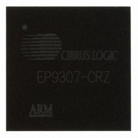
EP9307-CRZR Cirrus Logic Inc, EP9307-CRZR Datasheet - Page 153

EP9307-CRZR
Manufacturer Part Number
EP9307-CRZR
Description
IC Universal Platform ARM9 SOC Prcessor
Manufacturer
Cirrus Logic Inc
Series
EP9r
Specifications of EP9307-CRZR
Core Processor
ARM9
Core Size
16/32-Bit
Speed
200MHz
Connectivity
EBI/EMI, Ethernet, I²C, IrDA, Keypad/Touchscreen, SPI, UART/USART, USB
Peripherals
AC'97, DMA, I²:S, LCD, LED, MaverickKey, POR, PWM, WDT
Number Of I /o
14
Program Memory Type
ROMless
Ram Size
32K x 8
Voltage - Supply (vcc/vdd)
1.65 V ~ 3.6 V
Data Converters
A/D 8x12b
Oscillator Type
External
Operating Temperature
0°C ~ 70°C
Package / Case
272-LFBGA
Processor Series
EP93xx
Core
ARM920T
Data Bus Width
32 bit
3rd Party Development Tools
MDK-ARM, RL-ARM, ULINK2
Development Tools By Supplier
EDB9307A-Z
Lead Free Status / RoHS Status
Lead free / RoHS Compliant
Eeprom Size
-
Program Memory Size
-
Lead Free Status / Rohs Status
Details
Other names
Q5809834A
Available stocks
Company
Part Number
Manufacturer
Quantity
Price
Company:
Part Number:
EP9307-CRZR
Manufacturer:
Cirrus Logic Inc
Quantity:
10 000
- Current page: 153 of 824
- Download datasheet (13Mb)
DS785UM1
HC3IN:
HC3EN:
HC1IN:
HC1EN:
TIN:
U1EN:
EXVC:
U2EN:
Copyright 2007 Cirrus Logic
0 - GPIO Port H used for IDE
1 - GPIO Port H used for GPIO
HDLC3 clock in. This bit has no effect unless HC3EN is 1.
1 = pin EGPIO[3] is an input and drives an external HDLC
clock to UART3.
0 = pin EGPIO[3] is an output driven by UART3.
HDLC3 clock enable.
1 = pin EGPIO[3] is used to for an HDLC clock with
UART3.
0 = pin EGPIO[3] is not used.
HDLC1 clock in. This bit has no effect unless HC3EN is 0
and HC1EN is 1.
1 = pin EGPIO[3] is an input and drives an external HDLC
clock to UART1.
0 = pin EGPIO[3] is an output driven by UART1.
HDLC1 clock enable. This bit has no effect unless HC3EN
is 0.
1 = pin EGPIO[3] is used for an HDLC clock with UART1.
0 = pin EGPIO[3] is not used.
Touchscreen controller inactive.
1 - Touchscreen controller to inactive state,
0 - Touchscreen controller active.
To use the ADC converter independent of the Touch
screen controller, the Touchscreen controller must be
enabled and set inactive. The ADC can then be operated
using the direct access registers. The TIN bit does not
affect the ADC power state. ADC power down is directly
controlled by the ADCPD bit.
UART1 Enable.
1 - UART1 baud rate clock is active.
0 - UART1 clock is off.
External Video Clock.
1 - Raster engine uses external pixel clock and the SPCLK
pin is configured as an input,
0 - Raster engine uses internal pixel clock and the SPCLK
pin is configured as an output.
UART2 Enable.
1 - UART2 baud rate clock is active.
0 - UART2 clock is off.
EP93xx User’s Guide
System Controller
5-27
5
Related parts for EP9307-CRZR
Image
Part Number
Description
Manufacturer
Datasheet
Request
R

Part Number:
Description:
IC ARM9 SOC ARM920T 272TFBGA
Manufacturer:
Cirrus Logic Inc
Datasheet:

Part Number:
Description:
IC ARM9 SOC ARM920T 272TFBGA
Manufacturer:
Cirrus Logic Inc
Datasheet:

Part Number:
Description:
IC Universal Platform ARM9 SOC Prcessor
Manufacturer:
Cirrus Logic Inc

Part Number:
Description:
IC,MICROPROCESSOR,32-BIT,CMOS,BGA,272PIN,PLASTIC
Manufacturer:
Cirrus Logic Inc
Datasheet:

Part Number:
Description:
IC Universal Platform ARM9 SOC Prcessor
Manufacturer:
Cirrus Logic Inc
Datasheet:

Part Number:
Description:
Microcontrollers (MCU) IC Universal Platfrm ARM9 SOC Prcessor
Manufacturer:
Cirrus Logic Inc

Part Number:
Description:
Microcontrollers (MCU) IC Universal Platfrm ARM9 SOC Prcessor
Manufacturer:
Cirrus Logic Inc

Part Number:
Description:
MCU, MPU & DSP Development Tools Eval Bd Uni. ARM9 SOC Processor
Manufacturer:
Cirrus Logic Inc
Datasheet:

Part Number:
Description:
Development Kit
Manufacturer:
Cirrus Logic Inc
Datasheet:

Part Number:
Description:
Development Kit
Manufacturer:
Cirrus Logic Inc
Datasheet:

Part Number:
Description:
High-efficiency PFC + Fluorescent Lamp Driver Reference Design
Manufacturer:
Cirrus Logic Inc
Datasheet:

Part Number:
Description:
Development Kit
Manufacturer:
Cirrus Logic Inc
Datasheet:

Part Number:
Description:
Ref Bd For Speakerbar MSA & DSP Products
Manufacturer:
Cirrus Logic Inc


