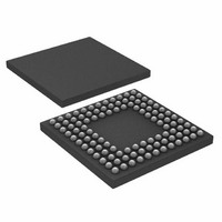
ADUC7122BBCZ-RL Analog Devices Inc, ADUC7122BBCZ-RL Datasheet - Page 65

ADUC7122BBCZ-RL
Manufacturer Part Number
ADUC7122BBCZ-RL
Description
PRECISION ANALOG MCU I.C
Manufacturer
Analog Devices Inc
Series
MicroConverter® ADuC7xxxr
Datasheet
1.ADUC7122BBCZ.pdf
(96 pages)
Specifications of ADUC7122BBCZ-RL
Core Processor
ARM7
Core Size
16/32-Bit
Speed
41.78MHz
Connectivity
I²C, SPI, UART/USART
Peripherals
POR, PWM, WDT
Number Of I /o
32
Program Memory Size
126KB (63K x 16)
Program Memory Type
FLASH
Ram Size
8K x 8
Voltage - Supply (vcc/vdd)
3 V ~ 3.6 V
Data Converters
A/D 13x12b, D/A 12x12b
Oscillator Type
Internal
Operating Temperature
-10°C ~ 95°C
Package / Case
108-LFBGA, CSPBGA
Lead Free Status / RoHS Status
Lead free / RoHS Compliant
Eeprom Size
-
Lead Free Status / RoHS Status
Lead free / RoHS Compliant
Other names
ADUC7122BBCZ-RL
ADUC7122BBCZ-RLTR
ADUC7122BBCZ-RLTR
Available stocks
Company
Part Number
Manufacturer
Quantity
Price
Company:
Part Number:
ADUC7122BBCZ-RL
Manufacturer:
Analog Devices Inc
Quantity:
10 000
Bit
2
1
0
I
Name:
Address:
Default Value:
Access:
Function:
Table 109. I2CxSSTA MMR Bit Designations
Bit
15
14
13
12-11
10
9:8
2
C Slave Status Registers
Name
I2CGCEN
ADR10EN
I2CSEN
Name
I2CSTA
I2CREPS
I2CID[1:0]
I2CSS
I2CGCID[1:0]
I2C0SSTA, I2C1SSTA
0xFFFF08AC, 0xFFFF092C
0x0000, 0x0000
Read only
This 16-bit MMR is the I
Description
I
Set this bit to enable the slave device to acknowledge an I
recognizes a data bit. If it receives a 0x06 (reset and write programmable part of the slave address by hardware) as
the data byte, the I
reset an entire I
data byte, the general call interrupt status bit sets on any general call.
The user must take corrective action by reprogramming the device address.
Set this bit to allow the slave ACK I
Clear to disable recognition of general call commands.
I
Set to 1 to enable 10-bit address mode.
Clear to 0 to enable normal address mode.
I
Set by the user to enable I
Clear to disable I
2
2
2
Description
Reserved bit.
This bit is set to 1 if a start condition followed by a matching address is detected. It is also set if a start byte (0x01) is
received, or if general calls are enabled and a general call code of 0x00 is received.
This bit is cleared upon receiving a stop condition.
This bit is set to 1 if a repeated start condition is detected.
This bit is cleared on receiving a stop condition.
I
00 = received address matches I2CxID0.
01 = received address matches I2CxID1.
10 = received address matches I2CxID2.
11 = received address matches I2CxID3.
I
This bit is set to 1 when a stop condition is detected after a previous start and matching address. When the
I2CSSENI bit in I2CxSCTL is set, an interrupt is generated.
This bit is cleared by reading this register.
I
00 = no general call received.
01 = general call reset and program address.
10 = general program address.
11 = general call matching alternative ID.
Note that these bits are not cleared by a general call reset command.
Clear these bits by writing a 1 to the I2CGCCLR bit in I2CxSCTL.
C general call enable.
C 10-bit address mode.
C slave enable bit.
2
2
2
C address matching register. These bits indicate which I2CxIDx register matches the received address.
C stop condition after start detected bit.
C general call ID bits.
2
C system. If it receives a 0x04 (write programmable part of the slave address by hardware) as the
2
C slave mode.
2
C interface resets as per the I
2
C status register in slave mode.
2
C slave mode.
2
C general call commands.
Rev. 0 | Page 65 of 96
2
C January 2000 bus specification. This command can be used to
2
C general call, Address 0x00 (write). The device then
ADuC7122


