ADSP-21160NCB-100 Analog Devices Inc, ADSP-21160NCB-100 Datasheet - Page 48
ADSP-21160NCB-100
Manufacturer Part Number
ADSP-21160NCB-100
Description
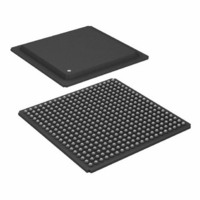
IC,DSP,32-BIT,CMOS,BGA,400PIN,PLASTIC
Manufacturer
Analog Devices Inc
Series
SHARC®r
Type
Floating Pointr
Specifications of ADSP-21160NCB-100
Rohs Status
RoHS non-compliant
Interface
Host Interface, Link Port, Serial Port
Clock Rate
100MHz
Non-volatile Memory
External
On-chip Ram
512kB
Voltage - I/o
3.30V
Voltage - Core
1.90V
Operating Temperature
-40°C ~ 100°C
Mounting Type
Surface Mount
Package / Case
400-BGA
Package
400BGA
Numeric And Arithmetic Format
Floating-Point
Maximum Speed
100 MHz
Ram Size
512 KB
Device Million Instructions Per Second
100 MIPS
Lead Free Status / RoHS Status
Available stocks
Company
Part Number
Manufacturer
Quantity
Price
Company:

Part Number:
ADSP-21160NCB-100
Manufacturer:
Analog Devices Inc
Quantity:
10 000


ADSP-21160M/ADSP-21160N
Table 37. ADSP-21160x Operation Types vs. Input Current
1
2
Table 38. External Power Calculations (ADSP-21160N Example)
Note that the conditions causing a worst-case P
from those causing a worst-case P
occur while 100% of the output pins are switching from all ones
to all zeros. Note also that it is not common for an application to
have 100% or even 50% of the outputs switching
simultaneously.
TEST CONDITIONS
The test conditions for timing parameters appearing in
ADSP-21160x specifications on page
time, output enable time, and capacitive loading.
Output Disable Time
Output pins are considered to be disabled when they stop driv-
ing, go into a high-impedance state, and start to decay from
their output high or low voltage. The time for the voltage on the
bus to decay by ΔV is dependent on the capacitive load, C
the load current, I
following equation:
The output disable time t
and t
val from when the reference signal switches to when the output
Operation
Instruction Type
Instruction Fetch
Core Memory Access
Internal Memory DMA
External Memory DMA
Data Bit Pattern for Core
Memory Access and DMA
Pin Type
Address
MS0
WRx
Data
CLKOUT
Peak activity = I
These assume a 2:1 core clock ratio. For more information on ratios and clocks (t
DECAY
as shown in
DD-INPEAK
t
DECAY
L
. This decay time can be approximated by the
No. of Pins
15
1
2
64
1
, high activity = I
2
= (C
Figure
DIS
L
ΔV)/I
is the difference between t
31. The time t
L
INT
DD-INHIGH
Peak Activity
Multifunction
Cache
2 per t
(DM
1 per 2 t
1 per External Port Cycle ( 64)
Worst Case
. Maximum P
17
% Switching
50
0
50
include output disable
, and low activity = I
CK
64 and PM
CCLK
Cycle
MEASURED
Cycles
EXT
1
INT
Rev. B | Page 48 of 60 | February 2010
are different
is the inter-
cannot
MEASURED
64)
DD-INLOW
L
and
× C
× 44.7 pF
× 44.7 pF
× 44.7 pF
× 14.7 pF
× 4.7 pF
. The state of the PEYEN bit (SIMD versus SISD mode) does not influence these calculations.
CK
and t
CCLK
High Activity
Multifunction
Internal Memory
1 per t
1 per 2 t
1 per External Port Cycle ( 64)
Random
(DM
voltage decays ΔV from the measured output high or output low
voltage. t
ΔV equal to 0.5 V.
), see the timing ratio definitions on page 20.
REFERENCE
SIGNAL
CK
× f
× 24 MHz
× 24 MHz
× 24 MHz
× 24 MHz
× 48 MHz
V
V
64)
CCLK
OH
OL
Cycle
DECAY
(MEASURED)
(MEASURED)
Cycles
1
is calculated with test loads C
P
EXT
Figure 31. Output Enable/Disable
t
DIS
OUTPUT STOPS
DRIVING
× V
× 10.9 V
× 10.9 V
× 10.9 V
× 10.9 V
× 10.9 V
DD
t
TEST CONDITIONS CAUSE THIS VOLTAGE
MEASURED
2
V
V
OH
OL
t
DECAY
TO BE APPROXIMATELY 1.5V
(MEASURED) – V
(MEASURED) + V
HIGH IMPEDANCE STATE.
Low Activity
Single Function
Internal Memory
None
None
None
N/A
L
= P
= 0.088 W
= 0.000 W
= 0.023 W
= 0.123 W
= 0.003 W
= 0.237 W
and I
OUTPUT STARTS
EXT
t
1.0V
ENA
2.0V
DRIVING
L
, and with
1
Related parts for ADSP-21160NCB-100
Image
Part Number
Description
Manufacturer
Datasheet
Request
R

Part Number:
Description:
±1.7g Dual-Axis IMEMS Accelerometer Evaluation Board
Manufacturer:
Analog Devices Inc
Datasheet:

Part Number:
Description:
Inertial Sensor Evaluation System
Manufacturer:
Analog Devices Inc
Datasheet:
Part Number:
Description:
Manufacturer:
Analog Devices Inc
Datasheet:
Part Number:
Description:
Manufacturer:
Analog Devices Inc
Datasheet:
Part Number:
Description:
Manufacturer:
Analog Devices Inc
Datasheet:
Part Number:
Description:
Manufacturer:
Analog Devices Inc
Datasheet:
Part Number:
Description:
Manufacturer:
Analog Devices Inc
Datasheet:
Part Number:
Description:
Manufacturer:
Analog Devices Inc
Datasheet:
Part Number:
Description:
Manufacturer:
Analog Devices Inc
Datasheet:
Part Number:
Description:
Manufacturer:
Analog Devices Inc
Datasheet:
Part Number:
Description:
Manufacturer:
Analog Devices Inc
Datasheet:
Part Number:
Description:
Manufacturer:
Analog Devices Inc
Datasheet:
Part Number:
Description:
Manufacturer:
Analog Devices Inc
Datasheet: