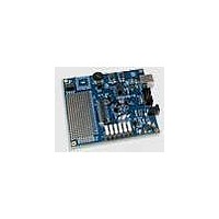
C8051F206DK-G Silicon Laboratories Inc, C8051F206DK-G Datasheet - Page 4

C8051F206DK-G
Manufacturer Part Number
C8051F206DK-G
Description
MCU, MPU & DSP Development Tools MCU DEVELOPMENT KIT W/ GLOBAL POWER SPLY
Manufacturer
Silicon Laboratories Inc
Datasheet
1.C8051F226DK.pdf
(146 pages)
Specifications of C8051F206DK-G
Processor To Be Evaluated
C8051F206
Data Bus Width
8 bit
Interface Type
USB
Lead Free Status / RoHS Status
Lead free / RoHS Compliant
C8051F2xx
10. Flash Memory ......................................................................................................... 85
11. On-Chip XRAM (C8051F206/226/236).................................................................... 90
12. Reset Sources......................................................................................................... 91
13. Oscillator ................................................................................................................. 97
14. Port Input/Output.................................................................................................. 101
15. Serial Peripheral Interface Bus ........................................................................... 110
16. UART...................................................................................................................... 117
17. Timers.................................................................................................................... 125
4
9.5. Power Management Modes .............................................................................. 83
10.1.Programming The Flash Memory ..................................................................... 85
10.2.Security Options ............................................................................................... 86
12.1.Power-on Reset................................................................................................ 92
12.2.Software Forced Reset..................................................................................... 92
12.3.Power-fail Reset ............................................................................................... 92
12.4.External Reset .................................................................................................. 93
12.5.Missing Clock Detector Reset .......................................................................... 93
12.6.Comparator 0 Reset ......................................................................................... 93
12.7.Watchdog Timer Reset..................................................................................... 93
13.1.External Crystal Example ............................................................................... 100
13.2.External RC Example ..................................................................................... 100
13.3.External Capacitor Example ........................................................................... 100
14.1.Port I/O Initialization ....................................................................................... 101
14.2.General Purpose Port I/O ............................................................................... 105
15.1.Signal Descriptions......................................................................................... 111
15.2.Serial Clock Timing......................................................................................... 113
15.3.SPI Special Function Registers ...................................................................... 113
16.1.UART Operational Modes .............................................................................. 118
16.2.Multiprocessor Communications .................................................................... 122
17.1.Timer 0 and Timer 1 ....................................................................................... 125
9.5.1. Idle Mode.................................................................................................. 83
9.5.2. Stop Mode ................................................................................................ 83
12.7.1.Watchdog Usage...................................................................................... 93
15.1.1.Master Out, Slave In .............................................................................. 111
15.1.2.Master In, Slave Out .............................................................................. 111
15.1.3.Serial Clock ............................................................................................ 111
15.1.4.Slave Select ........................................................................................... 111
16.1.1.Mode 0: Synchronous Mode .................................................................. 118
16.1.2.Mode 1: 8-Bit UART, Variable Baud Rate.............................................. 119
16.1.3.Mode 2: 9-Bit UART, Fixed Baud Rate .................................................. 121
16.1.4.Mode 3: 9-Bit UART, Variable Baud Rate.............................................. 121
17.1.1.Mode 0: 13-bit Counter/Timer ................................................................ 125
17.1.2.Mode 1: 16-bit Counter/Timer ................................................................ 126
17.1.3.Mode 2: 8-bit Counter/Timer with Auto-Reload...................................... 127
17.1.4.Mode 3: Two 8-bit Counter/Timers (Timer 0 Only)................................. 128
Rev. 1.6


