DLP-245SX DLP Design Inc, DLP-245SX Datasheet - Page 5
DLP-245SX
Manufacturer Part Number
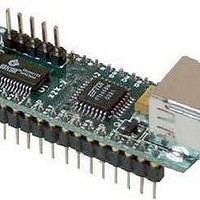
DLP-245SX
Description
Interface Modules & Development Tools USB/Micro Dev Board
Manufacturer
DLP Design Inc
Datasheet
1.DLP-245SX.pdf
(14 pages)
Specifications of DLP-245SX
Interface Type
USB
Data Bus Width
8 bit
Operating Supply Voltage
5.25 V
Product
Interface Modules
For Use With/related Products
SX28
Lead Free Status / RoHS Status
Lead free / RoHS Compliant


If you have VCP drivers installed on the PC that will be used to perform the EEPROM write
process, you must uninstall these drivers using the uninstaller program (included with the driver
files) and install the D2XX drivers prior to running the serializer utility.
QUICK START GUIDE
This guide requires the use of a Windows 98/2000/XP PC that is equipped with a USB port.
1. Download the DLL version of the device drivers from either dlpdesign.com or ftdichip.com.
2. The board can be configured to receive its operating power from the USB port or from user
3. Connect the DLP-245SX board to the PC via a standard A-B, 6-foot USB cable. This action
The DLP-245SX is shipped with default VID, PID, etc. values programmed into the EEPROM.
You only need to run the serializer program if you want to change the default values.
At this point, the DLP-245SX is ready for use. Note that the DLP-245SX will appear
non-responsive if data sent from the host PC is not read from the FT245BM device by the SX28
microcontroller.
If changing drivers from the VCP to the DLL type (or vice versa), you must first uninstall the
currently loaded drivers. This is accomplished by first disconnecting the DLP-245SX adapter
from the host computer and then running the uninstall program for the currently loaded version of
Unzip the drivers onto a blank floppy disk or into a folder on the hard drive.
electronics. Pins 14, 15, and 16 allow for this configuration. (Refer to the Pinout Description
in the next section for a detailed description of the DLP-245SX electrical interface.)
Note: The board will not operate until a power source has been selected as mentioned in
Step 2.
initiates the loading of the USB drivers. When prompted, select the folder where the DLL
version of the device drivers was stored in Step 1. Windows will then complete the
installation of the device drivers for the DLP-245SX board. The next time the DLP-245SX
board is attached, the host PC will immediately load the correct drivers without any
prompting. Reboot the PC if prompted to do so.
5
Related parts for DLP-245SX
Image
Part Number
Description
Manufacturer
Datasheet
Request
R

Part Number:
Description:
Zigbee / 802.15.4 Modules & Development Tools USE 626-DLP-RF2-Z
Manufacturer:
DLP Design Inc
Datasheet:
Part Number:
Description:
Zigbee / 802.15.4 Modules & Development Tools TTL SERIAL INTERFACE MODULE
Manufacturer:
DLP Design Inc
Datasheet:

Part Number:
Description:
MODULE USB-TO-TTL SRL UART CONV
Manufacturer:
DLP Design Inc
Datasheet:

Part Number:
Description:
Interface Modules & Development Tools FLASH2 TARGET BOARD 18F2321 w/IDE 2k Ltd
Manufacturer:
DLP Design Inc

Part Number:
Description:
Interface Modules & Development Tools FLASH2 TARGET BOARD 16F917 w/IDE 2k Ltd
Manufacturer:
DLP Design Inc

Part Number:
Description:
Interface Modules & Development Tools FLASH2 TARGET BOARD 18F4420 w/IDE 2k Ltd
Manufacturer:
DLP Design Inc
Part Number:
Description:
Zigbee / 802.15.4 Modules & Development Tools TTL SERIAL INTERFACE MODULE
Manufacturer:
DLP Design Inc
Datasheet:

Part Number:
Description:
Interface Modules & Development Tools USB FPGA Module w/ Xilinx XC3S400A
Manufacturer:
DLP Design Inc
Datasheet:

Part Number:
Description:
Interface Modules & Development Tools Dual Ch USB Adapter w/ FTDI FT2232H
Manufacturer:
DLP Design Inc
Datasheet:

Part Number:
Description:
MODULE DATA-ACQUISITION 8-CH
Manufacturer:
DLP Design Inc
Datasheet:

Part Number:
Description:
MODULE USB-MCU FT245RL W/16F877A
Manufacturer:
DLP Design Inc
Datasheet:

Part Number:
Description:
MODULE USB-TO-FPGA TRAINING TOOL
Manufacturer:
DLP Design Inc
Datasheet:

Part Number:
Description:
MODULE USB-MCU FT232R W/18F2410
Manufacturer:
DLP Design Inc
Datasheet:

Part Number:
Description:
MODULE USB-MCU FT245RL W/SX48
Manufacturer:
DLP Design Inc
Datasheet:

Part Number:
Description:
MODULE USB-MCU FT2232D W/16F877A
Manufacturer:
DLP Design Inc
Datasheet: