E3G-L35 Omron, E3G-L35 Datasheet - Page 16
E3G-L35
Manufacturer Part Number
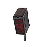
E3G-L35
Description
Photoelectric Sensors - Industrial CONVERGENT 200mm NPN CONN.
Manufacturer
Omron
Type
Photoelectric Sensorr
Series
E3Gr
Datasheet
1.E3G-L16.pdf
(17 pages)
Specifications of E3G-L35
Features
Light ON / Dark ON
Maximum Operating Temperature
+ 55 C
Minimum Operating Temperature
- 25 C
Operating Supply Voltage
10 V to 30 V
Sensing Distance
50 mm
Output Configuration
NPN
Sensing Method
Reflective, Diffuse
Sensing Object
Black Paper, Kodak® White Paper
Sensing Light
Infrared
Mounting Type
Bracket Mount
Current - Supply
65mA
Voltage - Supply
10 V ~ 30 V
Package / Case
Module, Connector
Lead Free Status / RoHS Status
Lead free / RoHS Compliant


E3G-L1/L3
Precautions
J DESIGNING
High-voltage Lines
Do not place sensor power supply or signal lines within the same
conduit as high-voltage power lines.
Voltage Ratings
Do not exceed rated supply voltage, ripple percent (for DC
models), or load current limits.
Ambient Lighting
Do not install the sensor in direct sunlight or other sources of
strong ambient light.
Environmental Conditions
Do not install the sensor in areas
$
$
$
Power Supply
If a switching power supply is used, or when using an inverter or
servomotor, you must ground the FG (frame ground) and G
(ground) terminals on the power supply for proper operation and
to avoid damaging the sensor.
Water Exposure
Although conforming to IP67, do not use the sensor where it may
be immsersed, is outdoors, or is exposed to rain.
To ensure the water resistance of the sensor, tighten the screws
of the operation panel cover to a torque of 0.2 to 0.3 N S m.
Cable
$
$
$
Avoiding Malfunctions
If using the photoelectric sensor with an inverter or servomotor,
be sure to ground the FG (frame ground) and G (ground)
terminals, otherwise the sensor may malfunction.
Proper Mounting Screws
Use M3 screws and washers to mount the sensor and bracket.
Mechanical Shock
Avoid mechanical shock during installation which may amage the
housing (see Shock specifications)
With high humidity, or where condensation would result
With corrosive gas.
With high vibration or shock.
The bending radius of the cable should be at least 25 mm.
When using extended power and signal cable, total length
must not exceed 100 m, with a minimum wire size of
0.3 mm
Do not apply tensile force exceeding 50 N to cable (pre-
leaded and connector models).
2
(22 AWG).
17
Short- -circuit Protection
If the load short- -circuits, the output will be turned off. Disconnect
power and check the wiring. After correcting the shorted
condition, turn power back on. The sensor will reset the
short-circuit protection function. The short-circuit protection is
activated when the current flow is at least 2.4 times the rated
load current. When using an inductive load, the inrush current
must not exceed this factor.
Connector
$
$
$
$
J MAINTENANCE AND INSPECTION
Cleaning
$
EEPROM Writing Error
$
When connecting or disconnecting the connector, hold the
connector cover to avoid tension on the housoing.
Tighten the connector by hand only. Do not use tools which
may damage the connector.
Always disconnect power before connecting or disconnecting
the connector.
Be sure that the connector is tightened securely. The sesnor
enclosure rating may be reduced or the connector may get
loosened.
Solvents damage the casing of the sensor. Do not use
solvents to clean the sensor.
If a teaching data error occurs with the operation indicator
flashing due to a power failure or static noise, perform the
teaching operation of the sensor again.
E3G-L1/L3
Related parts for E3G-L35
Image
Part Number
Description
Manufacturer
Datasheet
Request
R

Part Number:
Description:
CONVERGENT 50mm PNP CONN.
Manufacturer:
Omron
Datasheet:
Part Number:
Description:
Photoelectric Sensors - Industrial CONVERGENT 200MM PNP CONN
Manufacturer:
Omron
Datasheet:

Part Number:
Description:
Photoelectric Sensors - Industrial NPN/PNP POL RETRORFL
Manufacturer:
Omron
Datasheet:
Part Number:
Description:
Photoelectric Sensors - Industrial CONVERGENT 2M DC CONN.
Manufacturer:
Omron
Datasheet:
Part Number:
Description:
Photoelectric Sensors - Industrial RETRO 10M AC/DC TMR. SCREW TERM
Manufacturer:
Omron
Datasheet:

Part Number:
Description:
Photoelectric Sensors - Industrial CONVERGENT 2M AC/DC SCREW TERM
Manufacturer:
Omron
Datasheet:
Part Number:
Description:
Photoelectric Sensors - Industrial RETRO 10M AC/DC SCRE W TERM.
Manufacturer:
Omron
Datasheet:
Part Number:
Description:
Photoelectric Sensors - Industrial Retro 10M DC Connector
Manufacturer:
Omron
Datasheet:
Part Number:
Description:
Photoelectric Sensors - Industrial Retro 10M DC E39-R2 not incl.
Manufacturer:
Omron
Datasheet:
Part Number:
Description:
Photoelectric Sensors - Industrial NPN/PNP DIFF REFLECT
Manufacturer:
Omron
Datasheet:

Part Number:
Description:
G6S-2GLow Signal Relay
Manufacturer:
Omron Corporation
Datasheet:
Part Number:
Description:
Compact, Low-cost, SSR Switching 5 to 20 A
Manufacturer:
Omron Corporation
Datasheet:
Part Number:
Description:
Manufacturer:
Omron Corporation
Datasheet: