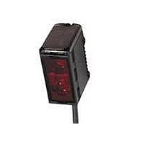
E3G-L36 Omron, E3G-L36 Datasheet

E3G-L36
Specifications of E3G-L36
Related parts for E3G-L36
E3G-L36 Summary of contents
Page 1
... Four-wire, vibration-proof, single-ended , cable bl 2 E3G-L1/L3 g Part number NPN PNP E3G-L11 E3G-L12 Setting range E3G-L15 E3G-L16 E3G-L31 E3G-L32 200 mm Setting range: White paper 50 to 200 mm E3G-L35 E3G-L36 Cable length Part number 2 m (6.56 ft) XS3F-M421-402 (16.40 ft) XS3F-M421-405-R XS3F-M422-402 (6.56 ft) XS3F-M422-405 (16.40 ft) ...
Page 2
... Infrared LED (860 nm dia. max. (at 150 mm sensing distance max. Operation or reset: 2.5 ms max. (This table continues on the next page.) 3 E3G-L1/L3 Part number E39-L139 E39-L140 E3G-L35 E3G-L36 ...
Page 3
... Load Reset Reset (relay) (relay) (Between brown and black) (Between blue and black) D-ON (Dark-ON) L-ON (Light-ON) Classification Wire color DC Brown White Blue Black 4 E3G-L1/L3 E3G-L35 E3G-L36 M8 connector Approx Dark- Incident OFF Interrupted Operation ON ON indicator OFF (orange Output OFF transistor ...
Page 4
... Distance (mm) E3G-L1j (in ZONE Mode) 2.5 Setting distance: 30 mm, 40 mm, 2 1 --0.5 --1.0 --1.5 --2 --2.5 Distance X (mm) E3G-L3j (in ZONE Mode) 4 Setting distance: 50 mm, 100 mm, 200 100 150 200 --1 200 mm --2 --3 100 mm --4 Distance X (mm) E3G-L3j 100 120 140 160 ...
Page 5
... Inclination angle " (#) E3G-L1j (Left and Right) 5 Target object: White paper 50 " Sensing distance: --1 --2 --3 --4 --5 --40 --30 --20 40 Inclination angle " (#) E3G-L1j (Left and Right) 5 Target object: White paper 50 " Sensing distance: --1 --2 --3 --4 --5 --40 --30 --20 40 Inclination angle " (#) E3G-L3j (Left and Right) ...
Page 6
... Distance (mm) J CLOSE-RANGE CHARACTERISTICS E3G-L1j 60 Setting distance Setting distance White paper White paper Black paper Material E3G-L3j (Left and Right) 10 Target object: White paper 50 " Sensing distance:150 --2 --4 --6 --8 Sensing object --10 --40 --30 --20 Inclination angle " (#) E3G-L3j 2.5 Target object: White paper ...
Page 7
... Black Mirror paper paper rubber Material E3G-L1V ( Setting Distance White Veneer Fiberboard Black Black Mirror paper paper rubber Material E3G-L3j ( Setting Distance White Veneer Fiberboard Black Black Mirror paper paper rubber Material E3G-L3j (at 150 mm Setting Distance) 180 150 120 White Veneer ...
Page 8
... Make sure not to install the sensor in the incorrect direction. Refer to the following. Target object Moving direction Moving direction Install the sensor as shown in the following if the target object greatly differs in color or material. Correct Moving direction 9 E3G-L1/L3 Correct Target object Moving direction Incorrect Target object Incorrect Moving direction ...
Page 9
... ON Threshold a (La) Threshold a (La) Background Background Part number E3G-L1j E3G-L3j Maximum sensing distance of E3G-L3 type may differ by color of the target object when setting distance is more than 150 mm (5.91 in). Confirm the operation of the sensor before actual operation. 10 E3G-L1/L3 3 Detection of glossy objects in $ front of the background. ...
Page 10
... The distance indicator (green) will turn ON. This means that teaching is successful. Set the mode selector to RUN to 5 complete the teaching operation. Set to L-ON or D-ON mode with the operation mode selector. 6 La: Distance equivalent to threshold (a) Operation 11 E3G-L1/L3 E3G-L ON Threshold a (La) Background Panel status NORM L NORM L OUT ZONE D NEAR ...
Page 11
... Distance indicator OUT (green) turns ON. (green) turns ON. OK NEAR ZONE D SET TEACH NG ADJ Threshold indicator (red) starts to flash. RUN FAR FAR Press E3G-L OFF Threshold a (La) ON Background Threshold b (Lb) OFF Panel status NORM L Distance indicator OUT OK (green) turns ON. NEAR ZONE D SET TEACH ...
Page 12
... The ON range can be shifted using the UP/DOWN selector and SET button. The differential travel is fixed. Control output Control output: ON DOWN (No change) 13 E3G-L1/L3 Panel status SET pressed with UP/ NORM L DOWN se- Threshold increases lector set to lector set to UP ...
Page 13
... Two, 8-dia. lens Emitter Six, Optical R1.6 axis Receiver 56.1 (2.21) 19.1 Model Model (0.75) E3G-L1j E3G- -L1j E3G-L3j E3G- -L3j 14 E3G-L1/L3 Distance indicator Threshold (green) indicator (red) Operation indicator (orange) 18.4 (0.72) Two, M3 through holes 40 A (1.57) B See table below ...
Page 14
... Mounting holes Two, M4 25.4 Two, R2.2 (1.00) Two, 8-dia. lens Emitter Six, R1.6 Optical axis Receiver 73.1 (2.88) 36.1 Model (1.42) E3G-L1j E3G-L3j 15 E3G-L1/L3 Distance indicator (green) Threshold indicator (red) Operation indicator (orange) 18.4 (0.72) Two, M3 through holes 40 (1.57 See table below ...
Page 15
... E3G-L1/L3 J MOUNTING BRACKETS E39-L139 Material: Stainless steel (SUS304) 10# Note: Provided with E3G-Lj1/-Lj2 J CONNECTOR CORDSETS Straight XS3F-M421-402 XS3F-M421-405 Right Angle XS3F-M422-402 XS3F-M422-405 E39-L140 Material: Stainless steel (SUS304) Note: Provided with E3G-Lj5/-Lj6 4 dia. 16 E3G-L1/L3 10# ...
Page 16
... J MAINTENANCE AND INSPECTION Cleaning Solvents damage the casing of the sensor. Do not use $ solvents to clean the sensor. EEPROM Writing Error If a teaching data error occurs with the operation indicator $ flashing due to a power failure or static noise, perform the teaching operation of the sensor again. 17 E3G-L1/L3 ...
Page 17
... OMRON ELECTRONICS LLC One East Commerce Drive Schaumburg, IL 60173 1-800-55-OMRON Cat. No. CEDSAX4 11/01 OMRON ON- -LINE Global -- http://www.omron.com USA -- http://www.omron.com/oei Canada -- http://www.omron.com/oci Specifications subject to change without notice. E3G-L1/L3 OMRON CANADA, INC. 885 Milner Avenue Scarborough, Ontario M1B 5V8 416-286-6465 Printed in U.S.A. ...


