HSDL-3602-008 Lite-On Electronics, HSDL-3602-008 Datasheet
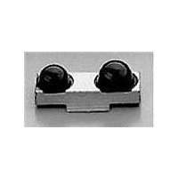
HSDL-3602-008
Specifications of HSDL-3602-008
Available stocks


Related parts for HSDL-3602-008


HSDL-3602-008 Summary of contents
Page 1
... IrDA® Data 1.4 Compliant 4 Mb/s 3V Infrared Transceiver Data Sheet Description The HSDL-3602 is a low profile infrared transceiver mod- ule that provides interface between logic and IR signals for through-air, serial, half-duplex IR data link. The mod- ule is compliant to IrDA Data Physical Layer Specifica- tions 1 ...
Page 2
... IrDA link. The HSDL-3602 comes with a front view packaging option (HSDL-3602-007/-037) and a top view packag- ing option (HSDL-3602-008/-038). It has an integrated shield that helps to ensure low EMI emission and high immunity to EMI field, thus enhancing reliable perfor- mance ...
Page 3
... Tantalum Notes: 5. CX1 must be placed within 0 the HSDL-3602 to obtain optimum noise immunity "HSDL-3602 Functional Block Diagram" on page assumed that Vled and V the 2 pins are powered by different supplies CX2 is applicable for Vled and CX1 for V CX2 on the V line can enhance supply rejection performance. ...
Page 4
... LEDA VOLTAGE (V) Marking Information HSDL-3602 Graph 1 The HSDL-3602-007/-037 is marked ‘3602YYWW’ on the shield where ‘YY’ indicates the unit’s manufacturing year, and ‘WW’ refers to the work week in which the unit is tested. [7] Absolute Maximum Ratings Parameter ...
Page 5
Recommended Operating Conditions Parameter Symbol Operating Temperature T A Supply Voltage V CC Logic High Input Voltage V IH for TXD, MD0, MD1, and FIR_SEL Logic Low Transmitter V IL Input Voltage LED (Logic High) Current I LEDA Pulse Amplitude ...
Page 6
... Pulse width specified is the pulse width of the second 500 kHz carrier pulse received in a data bit. The first 500 kHz carrier pulse may exceed 2 µs in width, which will not affect correct demodulation of the data stream. An ASK or DASK system using the HSDL-3602 has been shown to correctly receive all data bits for 9 µ ...
Page 7
TXD "Stuck ON" Protection TXD LED t pw (MAX.) LED Optical Waveform t pw LED ON 90% 50% 10% LED OFF RXD Output Waveform V OH 90% 50% 10 Receiver Wake Up Time Definition (when ...
Page 8
... HSDL-3602-007 and HSDL-3602-037 Package Outline with Dimension and Recommended PC Board Pad Layout 2.55 0.80 1.20 4.05 SIDE VIEW ALL DIMENSIONS IN MILLIMETERS (mm). DIMENSION TOLERANCE IS 0.20 mm UNLESS OTHERWISE SPECIFIED. PIN 10 0.70 4.95 10 CASTELLATION: PITCH 1.1 ± 0.1 CUMULATIVE 9.90 ± 0.1 BACK VIEW 8 6 ...
Page 9
... HSDL-3602-008 and HSDL-3602-038 Package Outline with Dimension and Recommended PC Board Pad Layout 0.36 0.53 0.47 0.31 0.83 0.31 2.08 0.42 0.84 0.94 4.65 9 11.7 5 2.5 0.85 0.3 1.46 2.57 3.24 3.84 5 12.2 +0.10 -0.00 +0.05 11.7 -0.00 0.1 3.85 4.16 +0.05 -0 ...
Page 10
... (MAX.) 4.4 A 5.20 ± 0. SECTION A-A 10 QUANTITY = 400 PIECES PER REEL (HSDL-3602-007) 1800 PIECES PER TAPE (HSDL-3602-037) (40 mm MIN.) EMPTY 2.00 ± 0.50 DIRECTION OF PULLING 5 6 2.00 ± 0.10 4.00 ± 0.10 Æ1.5 ± 0 8.00 ± 0.10 7 (400 mm MIN ...
Page 11
... Ao and Bo measured on a place 0.3 mm above the bottom of the pocket measured from a place on the inside bottom of the pocket to top surface of carrier. 5. Pocket position relative to sprocket hole measured as true position of pocket, not pocket hole. 11 QUANTITY = 400 PIECES PER REEL (HSDL-3602-008) 1800 PIECES PER TAPE (HSDL-3602-038) (40 mm MIN.) EMPTY 2.00 ± ...
Page 12
... Moisture Proof Packaging All HSDL-3602 options are shipped in moisture proof package. Once opened, moisture absorption begins. UNITS IN A SEALED MOISTURE-PROOF PACKAGE PACKAGE IS OPENED (UNSEALED) ENVIRONMENT LESS THAN 30 C, AND LESS THAN 60% RH PACKAGE IS NO BAKING YES OPENED LESS IS NECESSARY THAN 72 HOURS ...
Page 13
... The ∆T/∆time rates are detailed in the following table. The temperatures are measured at the component to printed circuit board connections. In process zone P1, the PC board and HSDL-3602 cas- tellation pins are heated to a temperature of 160°C to activate the flux in the solder paste. The temperature ramp up rate, R1, is limited to 4° ...
Page 14
... Appendix A: HSDL-3602-007/-037 SMT Assembly Application Note 1.0. Solder Pad, Mask, and Metal Solder Stencil Aperture STENCIL APERTURE SOLDER MASK Figure 1. Stencil and PCBA. HSDL-3602 fig 1.0 1.1. Recommended Land Pattern for HSDL-3602-007/-037 Dim 2.40 b 0.70 c (pitch) 1.10 d 2. ...
Page 15
... It is recommended that 2 fiducial cross be placed at mid-length of the pads for unit alignment. Note : Wet/Liquid Photo-Imagineable solder resist/mask is recommended LENS LAND h Y Figure 3. HSDL-3602-007/-037 PCBA-Adjacent land keep-out and solder mask. 15 inches min. 0.008 0.528 0.185 0.126 Rx LENS k SOLDER • ...
Page 16
... Aperture opening for shield pad per land dimension. SOLDER PASTE l Figure 4. Solder paste stencil aperture. HSDL-3602 fig 4.0 3.0. Pick and Place Misalignment Tolerance and Product Self-Alignment after Solder Reflow If the printed solder paste volume is adequate, the unit will self-align in the X-direction after solder reflow. ...
Page 17
Tolerance for X-axis Alignment of Castellation Misalignment of castellation to the land pad should not exceed 0 approximately half the width of the cas- tellation during placement of the unit. The castellations will completely self-align to the ...
Page 18
... LENS MINIMUM 1/2 THE LENGTH OF THE LAND PAD Y Figure 5. Section of a castellation in Y-axis. 3.4. Example of Good HSDL-3602-007/-037 Castellation HSDL-3602 fig 5.0 Solder Joints This joint is formed when the printed solder paste volume is adequate, i.e., 0.30 cubic mm and reflowed properly. It should be reflowed in IR Hot-air convection reflow oven ...
Page 19
... Appendix B: HSDL-3602-008/-038 SMT Assembly Application Note 1.0. Solder Pad, Mask, and Metal Solder Stencil Aperture STENCIL APERTURE SOLDER MASK Figure 1. Stencil and PCBA. HSDL-3602 fig 1.0 1.1. Recommended Land Pattern for HSDL-3602-008/-038 Dim 1.95 b 0.60 c (pitch) 1.10 d 1. ...
Page 20
Y-axis Misalignment of Castellation In the Y-direction, the unit does not self-align after sol- der reflow recommended that the unit be placed in line with the fiducial mark (mid-length of land pad). This will enable sufficient land ...
Page 21
... Resistor R1 should be selected to provide the appropri- ate peak pulse LED current over different ranges of Vcc. The recommended R1 for the voltage range 2.2 Ω while for 3 3 2.7 Ω. The HSDL- 3602 typically provides 250 mW/sr of intensity at the recommended minimum peak pulse LED current of 400 mA ...
Page 22
... HSDL-3602 Interoperability with National Semiconduc- tor PC97338VJG SIO Evaluation R eport Introduction The objective of this report is to demonstrate the in- teroperability of the HSDL-3602 IR transceiver IR mod- ule as wireless communication ports at the speed of 2.4 kb Mb/s with NS’s PC97338VJG Super I/O under typical operating conditions. Test Procedures ...
Page 23
... RLED = 2.2 Ω Optical transmitter pulse width = 125 ns Mode set to full power (ii) Test Result The interoperability test results show that HSDL-3602 IR transceiver can operate ≥ 1.5 meter link distance from 3.6 V with SMC 669/769 at any IrDA 1.1 data rate without error. ...
Page 24
... FDC37C669FR FDC37N769 FDC37C957/8FR HSDL-3602 Interoperability with SMC's Super I Controller IRRX STANDARD IRMODE MICROSYSTEM CORPORATION SUPER I CONTROLLER IRTX MODE GROUND FOR FULL POWER 24 IRTX IRRX 204 203 LEDA (10) RXD (8) FIR_SEL (3) HSDL-3602 TXD (9) SP CX1 MD0 MD1 CX2 4 5 OPERATION V (1) CC IRMODE 23 21 ...
Page 25
... In the figure below the width of the window the height of the window and Z is the distance from the HSDL-3602 to the back of the window. The distance from the center of the LED lens to the center of the photodiode lens 7.08mm. The equations for com- ...
Page 26
... The depth of the LED image inside the HSDL-3602 8mm. ‘A’ is the required half angle for viewing. For IrDA 0 compliance, the minimum is 15 and the maximum Assuming the thickness of the window to be neg- ligible, the equations result in the following tables and ...
Page 27
... In all cases, the center thickness of the window is 1.5 mm, the window is made of polycarbonate plastic, and the distance from the transceiver to the back surface of the window is 3 mm. Curved Front and Back (Second choice) HSDL-3602 Curved Window WWW.liteon.com or Curved Front, Flat Back (Do not use) HSDL-3602 Curved/Flat Window ...