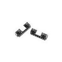
HSDL-3201#021 Lite-On Electronics, HSDL-3201#021 Datasheet

HSDL-3201#021
Specifications of HSDL-3201#021
Available stocks
Related parts for HSDL-3201#021
HSDL-3201#021 Summary of contents
Page 1
... HSDL-3201 ® IrDA Data 1.4 Low Power Compliant 115.2 kb/s Infrared Transceiver Data Sheet Features • Ultra small surface mount package • Minimal height: 2.5 mm • V from 2.7 to 3.6 volts CC • Withstands > 100 mV power supply ripple p-p • LED supply voltage can range from 2.7 to 6.0 volts • ...
Page 2
... IrDA Data 1.4 (low power) physical layer specifications. The HSDL-3201 meets the 20 cm link distance to other IrDA 1.4 low power devices, and link distance to IrDA 1.4 standard devices. HSDL-3201#021 Pinout, Rear View ...
Page 3
... No Signal High Don’t care High 6 Shutdown Mode Notes When the HSDL-3201 is in Shutdown Mode (SD pin high), the part presents different impedances to the rest of the circuit than when normal mode. RXD Pin: This pin is NOT Tri-state. During shutdown the equivalent circuit is a weak pullup ( ~ 300 ...
Page 4
Recommended Operating Conditions Parameter Operating Temperature Supply Voltage LED Supply Voltage TXD, SD Input Logic High Voltage Logic Low Receiver Input Logic High Irradiance Logic Low Receiver Data Rate RXD Output Waveform 90% 50% 10% V ...
Page 5
Electrical & Optical Specifications Specifications hold over the recommended operating conditions unless otherwise noted. Unspecified test conditions may be anywhere in their operating range. All typical values are and 3.0 V unless otherwise noted. Parameter Symbol Receiver ...
Page 6
... Notes must be placed within 0 the HSDL-3201 to obtain optimum noise immunity TXD is stuck in the high state, the LED will turn off after about RXD will echo the TXD signal while TXD is transmitting data. 4. In-Band IrDA signals and data rates 115.2 Kb/s. 5. RXD Logic Low is a pulsed response. The pulse width is 2.4 s, independent of data rate. ...
Page 7
... HSDL-3201#021 Package Dimensions MOUNTING CENTER 2.05 RECEIVER 1.175 2.85 3.0 1.85 PIN1 0.6 7 4.0 1.025 C L EMITTER 2.2 2.5 1.05 1.25 2.55 4.0 8.0 2 UNIT: mm TOLERANCE: ± 0.2 mm COPLANARITY = 0.1 mm MAX. PIN 1 3.325 6.65 0.35 0.65 0.80 ...
Page 8
... HSDL-3201#021 Tape and Reel Dimensions UNIT: mm POLARITY PIN 8: VLED PIN 1: GND 0.4 ± 0.05 2.8 ± 0.1 EMPTY (40 mm MIN.) LABEL 8 4.0 ± 0.1 1.75 ± 0.1 + 0.1 1.5 1.5 ± 0.1 0 7.5 ± 0.1 8.4 ± 0.1 3.4 ± 0.1 8.0 ± ...
Page 9
... HSDL-3201#008 Package Dimensions 2 2.8 3.35 2.35 0.7 ± 0.1 PIN1 Pin Symbol Description 1 GND Ground Connection 3 V Supply Voltage CC 4 AGND Analog Ground 5 SD Shutdown (Active High) 6 RxD Receive Data 7 TxD Transmit Data 8 VLED LED Voltage 9 EMI Shield EMI Shield 9 +0.05 2 ...
Page 10
... HSDL-3201#008 Tape and Reel Dimensions 60°TYP. 264 5°(MAX.) 5° 3.1 ± 0.1 A-A SECTION UNIT: mm SYMBOL Ao Bo SPEC 3.65 ± 0.10 7.90 ± 0.10 SYMBOL E SPEC 1.75 ± 0.10 7.50 ± 0.10 NOTES SPROKET HOLE PITCH CUMULATIVE TOLERANCE IS ± 0.2 mm. ...
Page 11
... Time In reels hours 100 C 4 hours In bulk 125 C 2 hours 150 C 1 hour Baking should only be done once. 11 Recommended Land Pattern for HSDL-3201#021 (Front Options MOUNTING CENTER 0.10 1.75 0.60 0.475 UNIT: mm Recommended Land Pattern for HSDL-3201#008 (Top Options) 2.20 1.45 ...
Page 12
... Appendix A: HSDL-3201#021 SMT Assembly Application Note Solder Pad, Mask, and Metal Stencil STENCIL APERTURE SOLDER MASK Recommended Metal Solder Stencil Aperture It is recommended that only a 0.127 mm (0.005 inches 0.11 mm (0.004 inches) thick stencil be used for solder paste printing. This is to ensure adequate printed solder paste volume and no shorting ...
Page 13
Adjacent Land Keep-Out and Solder Mask Areas Adjacent land keep-out is the maximum space occupied by the unit relative to the land pattern. There should be no other SMD components within this area. The minimum solder resist strip width required ...
Page 14
PCB Layout Suggestion The following PCB layout shows a recommended layout that should result in good electrical and EMI performance. Things to note: 1. The ground plane should be continuous under the part, but should not extend under the shield ...
Page 15
... FIDUCIAL Y-axis Misalignment of Castellation In the Y direction, the HSDL-3201 does not self align after solder reflow. Avago recommends that the part be placed in line with the fiducial mark (mid- length of land pad.) This will enable ...
Page 16
... The cool down rate, R5, from the liquidus point of the solder (77 F) should not exceed 6 C per second maximum. This limitation is necessary to allow the PC board and HSDL-3201 castellation I/O pins to change dimensions evenly, putting minimal stresses on the HSDL-3201 transceiver. ...
Page 17
... the width of the window the height of the window, and Z is the distance from the HSDL-3201 to the back of the window. The distance from the center of the LED lens to the center of the photodiode lens is 5.1 mm. The equations for the size of the window are as follows ...
Page 18
Shape of the Window From an optics standpoint, the window should be flat. This ensures that the window will not alter either the radiation pattern of the LED, or the receive pattern of the photodiode. If the window must be ...
Page 19
Test Methods Background Light and Electromagnetic Field There are four ambient interference conditions in which the receiver is to operate correctly. The conditions are to be applied separately: 1. Electromagnetic field: 3 V/m maximum (please refer to IEC 801-3, severity ...
Page 20
For company and product information, please go to our web site: http://optodatabook.liteon.com/databook/databook.aspx Data subject to change. Copyright © 2007 Lite-On Technology Corporation. All rights reserved. WWW.liteon.com or ...


