HSDL-3000#007 Lite-On Electronics, HSDL-3000#007 Datasheet - Page 11
HSDL-3000#007
Manufacturer Part Number
HSDL-3000#007
Description
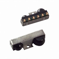
Infrared Transceivers IR Transceiver 115.2Kb/s
Manufacturer
Lite-On Electronics
Datasheet
1.HSDL-3000007.pdf
(14 pages)
Specifications of HSDL-3000#007
Wavelength
875 nm
Continual Data Transmission
115.2 Kbit/s
Transmission Distance
1.5 m
Radiant Intensity
75 mW/sr
Half Intensity Angle Degrees
30 deg to 60 deg
Pulse Width
7.5 us, 1.6 us
Maximum Rise Time
100 ns, 600 ns
Maximum Fall Time
100 ns, 600 ns
Led Supply Voltage
0 V to 7 V
Operating Voltage
2.7 V to 5.5 V
Maximum Operating Temperature
+ 70 C
Minimum Operating Temperature
- 20 C
Dimensions
9.1 mm x 3.65 mm x 2.7 mm
Data Rate
115.2kbs (SIR)
Idle Current, Typ @ 25° C
0.02µA
Link Range, Low Power
1.5m
Operating Temperature
-20°C ~ 70°C
Orientation
Side View
Shutdown
*
Size
9.1mm x 3.65mm x 2.7mm
Standards
IrPHY 1.3
Supply Voltage
2.7 V ~ 5.5 V
Lead Free Status / Rohs Status
Lead free / RoHS Compliant
Available stocks
Company
Part Number
Manufacturer
Quantity
Price


1.2 Adjacent Land Keep-out and Solder Mask Areas
• Adjacent land keep-out is the maximum space
• “h” is the minimum solder resist strip width required
• It is recommended that 2 fiducial cross be placed at
Note: Wet/Liquid Photo-Imageable solder resist/mask is
recommended.
2.0 Recommended Solder Paste/Cream Volume for
Castellation Joints
The recommended printed solder paste volume required
per castellation pad is 0.30 cubic mm (based on either
no-clean or aqueous solder cream types with typically
60 to 65% solid content by volume).
Figure 3. HSDL-3000#007/#017 PCBA – Adjacent land keep-out and solder mask.
11
Dim.
h
j
k
l
occupied by the unit relative to the land pattern.
There should be no other SMD components within
this area.
to avoid solder bridging adjacent pads.
mid-length of the pads for unit alignment.
LAND
mm
min. 0.40
10.1
3.85
3.2
Rx LENS
HSDL-3000 fig 3.0 PCBA Land Keep-Out
h
Inches
min. 0.016
0.40
0.15
0.126
j
Y
Tx LENS
X
SOLDER
MASK
k
l
2.1 Recommended Metal Solder Stencil Aperture
It is recommended that only 0.152 mm (0.006 inches) or
0.127 mm (0.005 inches) thick stencil be used for solder
paste printing. This is to ensure adequate printed solder
paste volume and no shorting. The following combina-
tion of metal stencil aperture and metal stencil thick-
ness should be used:
w, the width of aperture, is fixed at 0.85 mm (0.034 inches).
Aperture opening for shield pad is 3.05 mm x 1.1 mm as per land dimen-
sion.
Figure 4. Solder paste stencil aperture.
t, Nominal Stencil Thickness
mm
0.152
0.127
APERTURES AS PER
LAND DIMENSIONS
SOLDER PASTE
l
inches
0.006
0.005
HSDL-300 Solder Stencil
mm
2.3 ± 0.05
2.75 ± 0.05
l, Length of Aperture
w
inches
0.091 ± 0.002
0.108 ± 0.002
t (STENCIL THICKNESS)
See Fig. 4.
Related parts for HSDL-3000#007
Image
Part Number
Description
Manufacturer
Datasheet
Request
R

Part Number:
Description:
EMITTER IR 5MM 875NM
Manufacturer:
Lite-On Electronics
Datasheet:

Part Number:
Description:
Infrared Transceivers IR Transceiver 115.2Kb/s
Manufacturer:
Lite-On Electronics
Datasheet:
Part Number:
Description:
Infrared Transceivers IR Transceiver 115.2Kb/s
Manufacturer:
Lite-On Electronics
Datasheet:
Part Number:
Description:
Infrared Transceivers IR Transceiver 115.2Kb/s
Manufacturer:
Lite-On Electronics
Datasheet:

Part Number:
Description:
Infrared Transceivers IR Transceiver 115Kb/s
Manufacturer:
Lite-On Electronics
Datasheet:

Part Number:
Description:
Infrared Transceivers IR Transceiver 115.2Kb/s
Manufacturer:
Lite-On Electronics

Part Number:
Description:
Infrared Transceivers IR Transceiver
Manufacturer:
Lite-On Electronics
Datasheet:
Part Number:
Description:
IRDA TX/RX 0.1152Mbps 3.3V 8-Pin Ultra Small Profile T/R
Manufacturer:
Lite-On Electronics
Datasheet:
Part Number:
Description:
IRDA TX/RX 0.1152Mbps 3.3V 8-Pin T/R
Manufacturer:
Lite-On Electronics
Datasheet:

Part Number:
Description:
Infrared Transceivers IR Transceiver 115.2Kb/s
Manufacturer:
Lite-On Electronics
Datasheet:
Part Number:
Description:
ENCODER/DECODER 3/16 8-SOIC
Manufacturer:
Lite-On Electronics
Datasheet:

Part Number:
Description:
OPTOCOUPLER HS LOGIC OUT 8-DIP
Manufacturer:
Lite-On Electronics
Datasheet:

Part Number:
Description:
OPTOCOUPLER HS TRANS OUT 8-DIP
Manufacturer:
Lite-On Electronics
Datasheet:

Part Number:
Description:
OPTOCOUPLER HS TRANS OUT 8-SMD
Manufacturer:
Lite-On Electronics
Datasheet:

Part Number:
Description:
OPTOCOUPLER HS TRANS OUT 8-DIP
Manufacturer:
Lite-On Electronics
Datasheet: