HSDL-3000#007 Lite-On Electronics, HSDL-3000#007 Datasheet
HSDL-3000#007
Specifications of HSDL-3000#007
Available stocks


Related parts for HSDL-3000#007


HSDL-3000#007 Summary of contents
Page 1
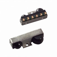
... Such features are ideal for battery-operated handheld products. The HSDL-3000 has two front packaging type options (HSDL-3000#007/017). Both options have an integrated shield that helps to ensure low EMI emission and high immunity to EMI field, thus enhancing reliable perfor- mance. ...
Page 2
... REAR VIEW from 2.7 to 5.5 volts. CC Marking Information The HSDL-3000#007/017 is marked with a number “0” and “YWWLL” on the shield where ‘Y’ indicates the unit’s manufacturing year, ‘WW’ refers to the work week and ‘LL’ is the lot information. ...
Page 3
Absolute Maximum Ratings For implementations where case to ambient thermal resistance is ≤ 50°C/W. Parameter Storage Temperature Operating Temperature LED Supply Voltage Supply Voltage Output Voltage: RXD LED Current Pulse Amplitude Recommended Operating Conditions Parameter Symbol Operating Temperature T –20 ...
Page 4
Electrical & Optical Specifications Specifications (Min. and Max. values) hold over the recommended operating conditions unless otherwise noted. Unspecified test conditions may be any- where in their operating range. All typical values (Typ.) are at 25°C with V Parameter Symbol ...
Page 5
... V (LEDA) ON ILED vs. V (LEDA). ON HSDL-3000 Graph 2 Conditions V ≥ ≤ V ≤ ≥ V – 0. 25° (TXD) ≤ (TXD) ≥ 110 100 2.20 1.80 220 260 300 340 380 420 ILED (mA) IE vs. ILED. H HSDL-3000 Graph 3 460 500 ...
Page 6
... HSDL-3000#007 and HSDL-3000#017 Package Outline with Dimension and Recommended PC Board Pad Layout 1.35 1.25 0.70 2.95 1 0.425 1. 9.10 ± 0.15 2.65 2.60 5. PITCH 1.55 (5X) 0.65 (4 PLACES) RECOMMENDED LAND PATTERN 3.13 3. 0.25 1.55 8.60 2.70 ± 0.15 1.55 3.65 0.60 (2 PLACES) DIMENSIONS ...
Page 7
... HSDL-3000#007 and HSDL-3000#017 Tape and Reel Dimensions 5.00 (MAX.) POLARITY PIN 6: GND + 9.50 ± 0.10 PIN 1: VLED 0.40 ± 0.10 3.00 ± 0.10 MATERIAL OF CARRIER TAPE: CONDUCTIVE POLYSTYRENE MATERIAL OF COVER TAPE: PVC METHOD OF COVER: HEAT ACTIVATED ADHESIVE DETAIL A LABEL 7 4.00 ± 0.10 1.13 ± ...
Page 8
... Moisture Proof Packaging The HSDL-3000 is shipped in moisture proof packaging. Once opened, moisture absorption begins. Recommended Storage Conditions Storage Temperature 10°C to 30°C Relative Humidity Below 60 Time from Unsealing to Soldering After removal from the bag, the parts should be soldered within three days if stored at the recommended storage conditions ...
Page 9
... The temperatures are measured at the component to printed circuit board connections. In process zone P1, the PC board and HSDL-3000 pins are heated to a temperature of 150°C to activate the flux in the solder paste. The temperature ramp up rate, R1, is limited to 3°C per second to allow for even heating of both the PC board and HSDL-3000 pins ...
Page 10
... Appendix A : HSDL-3000#007/#017 SMT Assembly Application Note 1.0 Solder Pad, Mask and Metal Solder Stencil Aperture STENCIL APERTURE SOLDER MASK Figure 1. Stencil and PCBA. 1.1 Recommended Land Pattern for HSDL-3000 DIM. mm INCHES a 2.30 0.091 b 0.85 0.034 c (PITCH) 1.55 0.061 d 1.10 0.043 e 3 ...
Page 11
... Rx LENS LAND h Y Figure 3. HSDL-3000#007/#017 PCBA – Adjacent land keep-out and solder mask. HSDL-3000 fig 3.0 PCBA Land Keep-Out 11 2.1 Recommended Metal Solder Stencil Aperture It is recommended that only 0.152 mm (0.006 inches) or 0.127 mm (0.005 inches) thick stencil be used for solder paste printing ...
Page 12
... Appendix B: HSDL-3000#007/#017 – Recommended Optical Port Design To insure IrDA compliance, some constraints on the height and width of the window exist. The minimum di- mensions ensure that the IrDA cone angles are met with- out vignetting. The maximum dimensions minimize the effects of stray light. The minimum size corresponds to a cone angle of 30 degrees, the maximum cone angle of 60 degrees ...
Page 13
... In all cases, the center thickness of the window is 1.5 mm, the window is made of polycarbonate plastic, and the distance from the transceiver to the back surface of the window is 3 mm. Curved Front and Back HSDL-3000 Curved Window (second choice) HSDL-3000 Curved/Flat Window Curved Front, Flat Back (do not use) ...
Page 14
Test Methods Background Light and Electro-magnetic Field There are four ambient interference conditions in which the receiver is to operate correctly. The conditions are to be applied separately: 1. Electromagnetic field: 3 V/m maximum (please refer to IEC 61000-4-3 severity ...