HSDL-3612-038 Lite-On Electronics, HSDL-3612-038 Datasheet
HSDL-3612-038
Specifications of HSDL-3612-038


Related parts for HSDL-3612-038


HSDL-3612-038 Summary of contents
Page 1
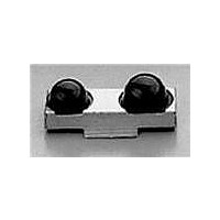
... IrDA® Data Compliant 115.2 kb Infrared Transceiver Data Sheet Description The HSDL-3612 is a low-profile infrared transceiver module that provides interface between logic and IR signals for through-air, serial, half-duplex IR data link. The module is compliant to IrDA Data Physical Layer Specifications 1.4 and IEC825-Class 1 Eye Safe. Applications • Digital imaging – Digital still cameras – Photo-imaging printers • ...
Page 2
... Application Support Information The Application Engineering group is available to assist you with the technical understanding associated with HSDL-3612 infrared transceiver module. You can contact them through your local sales representatives for ad- ditional details. Package Part Number Front View HSDL-3612-007 Front View HSDL-3612-037 Top View HSDL-3612-008 Top View HSDL-3612-038 Standard Package Increment 400 1800 400 1800 ...
Page 3
... Notes: 1. In-Band El ≤ 115.2 kb/s. 2. Logic Low is a pulsed response. The condition is maintained for duration dependent on the pattern and strength of the incident intensity maintain low shutdown current, TXD needs to be driven high or low and not left floating. 3 Symbol V CC AGND GND MD0 BACK VIEW (HSDL-3612-007/-037) MD1 NC GND RXD TXD LEDA BOTTOM VIEW (HSDL-3612-008/-038) RX Function Shutdown SIR SIR SIR Inputs EI X [1] High Low ...
Page 4
... LEDA VOLTAGE (V) ILED vs. LEDA. Marking Information The HSDL-3612-007/-037 is marked “3612YYWW” on the shield where “YY” indicates the unit’s manufactur- ing year, and “WW” refers to the work week in which the unit is tested. CAUTIONS: The BiCMOS inherent to the design of this component increases the component’s susceptibility to dam- age from electrostatic discharge (ESD) ...
Page 5
Absolute Maximum Ratings Parameter Symbol Storage Temperature T S Operating Temperature LED Current I LED Peak LED Current I LED LED Anode Voltage V LEDA Supply Voltage Vcc Transmitter Data I TXD Input Current Receiver Data V O Output Voltage Note: 6. For implementations where case to ambient thermal resistance ≤ 50°C/W. Recommended Operating ...
Page 6
Electrical & Optical Specifications Specifications hold over the Recommended Operating Conditions unless otherwise noted. Unspecified test condi- tions can be anywhere in their operating range. All typical values are at 25°C and 3.3 V unless otherwise noted. Parameter Transceiver Supply Shutdown Current Idle Digital Input Logic Current Low/High Transmitter Transmitter Logic High Radiant Intensity Intensity Peak Wavelength Spectral Line Half Width Viewing Angle Optical Pulse ...
Page 7
Electrical & Optical Specifications Specifications hold over the Recommended Operating Conditions unless otherwise noted. Unspecified test condi- tions can be anywhere in their operating range. All typical values are at 25°C and 3.3 V unless otherwise noted. Parameter Receiver [7] Receiver Logic Low Data Output Voltage Logic High Viewing Angle 2θ Logic High Receiver Input Irradiance Logic Low Receiver Input Irradiance Receiver Peak Sensitivity Wavelength Receiver SIR Pulse Width Receiver Latency Time Receiver Rise/Fall Times Receiver Wake Up Time Notes: 7. Logic Low is a pulsed response. The condition is maintained for duration dependent on pattern and strength of the incident intensity. ...
Page 8
TXD “Stuck ON” Protection TXD LED t pw (MAX.) RXD Output Waveform V OH 90% 50% 10 LED Optical Waveform LED ON 90% 50% 10% LED OFF t r Receiver Wake Up Time Definition (when MD0 ...
Page 9
... HSDL-3612-007 and HSDL3612-037 Package Outline with Dimension and Recommended PC Board Pad Layout PIN FUNCTION PIN FUNCTION AGND 7 GND 3 GND 8 RXD 4 MD0 9 TXD 5 MD1 10 LEDA 2.45 0.80 1.20 4.05 SIDE VIEW ALL DIMENSIONS IN MILLIMETERS (mm). DIMENSION TOLERANCE IS 0.20 mm UNLESS OTHERWISE SPECIFIED. PIN 10 0.70 4 ...
Page 10
... HSDL-3612-008 and HSDL3612-038 Package Outline with Dimension and Recommended PC Board Pad Layout 0.36 0.53 0.47 0.31 0.83 0.31 2.08 0.42 0.84 0.94 4.65 10 11.7 5 2.5 0.85 0.3 1.46 2.57 3.24 3.84 5 12.2 +0.10 -0.00 +0.05 11.7 -0.00 0.1 3.85 +0.05 4.16 -0 ...
Page 11
... (MAX.) 4.4 A 5.20 ± 0. SECTION A-A 11 QUANTITY = 400 PIECES PER REEL (HSDL-3612-007) 1800 PIECES PER TAPE (HSDL-3612-037) (40 mm MIN.) EMPTY 2.00 ± 0.50 DIRECTION OF PULLING 5 6 2.00 ± 0.10 4.00 ± 0.10 Æ1.5 ± 0 8.00 ± 0.10 7 (400 mm MIN ...
Page 12
... Ko measured from a place on the inside bottom of the pocket to top surface of carrier. 5. Pocket position relative to sprocket hole measured as true position of pocket, not pocket hole. 12 QUANTITY = 400 PIECES PER REEL (HSDL-3612-008) 1800 PIECES PER TAPE (HSDL-3612-038) (40 mm MIN.) EMPTY 2.00 ± 0.50 ...
Page 13
... Moisture Proof Packaging All HSDL-3612 options are shipped in moisture proof package. Once opened, moisture absorption begins. Baking Conditions If the parts are not stored in dry conditions, they must be baked before reflow to prevent damage to the parts. Package Temp. In reels 60°C In bulk 100°C 125°C 150°C Baking should be done only once. NO BAKING YES IS NECESSARY 13 Recommended Storage Conditions Storage ...
Page 14
... The ∆T/∆time rates are detailed in the above table. The temperatures are measured at the component to printed circuit board connections. In process zone P1, the PC board and HSDL-3612 cas- tellation pins are heated to a temperature of 160°C to activate the flux in the solder paste. The temperature ramp up rate, R1, is limited to 4°C per second to allow for even heating of both the PC board and HSDL-3612 castellations ...
Page 15
... Appendix A: HSDL-3612-007/-037 SMT Assembly Application Note 1.0 Solder Pad, Mask and Metal Solder Stencil Aperture STENCIL APERTURE SOLDER MASK Figure 1.0. Stencil and PCBA. 1.1 Recommended Land Pattern for HSDL-3612-007/-037 Dim 2.40 b 0.70 c (pitch) 1.10 d 2.35 e 2.80 f 3.13 g 4.31 Tx LENS 10x PAD FIDUCIAL Figure 2.0. Top view of land pattern. ...
Page 16
... It is recommended that 2 fiducial cross be placed at mid-length of the pads for unit alignment. Note: Wet/Liquid Photo-Imaginable solder resist/mask is recommended LENS LAND h Y Figure 3.0. HSDL-3612-007/-037 PCBA – Adjacent land keep-out and solder mask. 2.0 Recommended Solder Paste/Cream Volume for Castellation Joints Based on calculation and experiment, the printed solder paste volume required per castellation pad is 0.30 cubic mm (based on either no-clean or aqueous solder cream types with typically 60 to 65% solid content by volume LENS DIM ...
Page 17
Recommended Metal Solder Stencil Aperture It is recommended that only 0.152 mm (0.006 inches) or 0.127 mm (0.005 inches) thick stencil be used for solder paste printing. This is to ensure adequate printed solder paste volume and no shorting. The following combina- tion of metal stencil aperture and metal stencil thick- ness should be used: See Fig 4.0 t, nominal stencil thickness mm inches 0.152 0.006 0.127 0.005 w, the width of aperture is fixed at 0.70 mm (0.028 inches) Aperture opening for shield pad per land dimensions SOLDER PASTE l Figure ...
Page 18
Tolerance for X-axis Alignment of Castellation Misalignment of castellation to the land pad should not exceed 0 approximately half the width of the castellation during placement of the unit. The castel- lations will completely self-align to the pads during solder reflow as seen in the pictures below. Photo 1.0. Castellation misaligned to land pads in x-axis before reflow. 3.2 Tolerance for ...
Page 19
... This will enable sufficient land length (minimum of land length.) to form a good joint. See Fig 5.0. 3.4 Example of Good HSDL-3612-007/-037 Castella- tion Solder Joints This joint is formed when the printed solder paste volume is adequate, i.e. 0.30 cubic mm and reflowed properly ...
Page 20
... Appendix B: HSDL-3612-008/-038 SMT Assembly Application Note 1.0. Solder Pad, Mask, and Metal Solder Stencil Aperture STENCIL APERTURE SOLDER MASK Figure 1. Stencil and PCBA. 1.1. Recommended Land Pattern for HSDL-3612-008/-038 Dim 1.95 b 0.60 c (pitch) 1.10 d 1.60 e 5.70 f 3.80 g 2. LENS b a FIDUCIAL 10x PAD 20 METAL STENCIL FOR SOLDER PASTE ...
Page 21
Y-axis Misalignment of Castellation In the Y-direction, the unit does not self-align after sol- der reflow recommended that the unit be placed in line with the fiducial mark (mid-length of land pad). This will enable sufficient land length (minimum of length) to form a good joint. See Figure 2. Y 1/2 THE LENGTH OF THE CASTELLATION PAD Figure 2. Section of a castellation in Y-axis land 2 FIDUCIAL ...
Page 22
... Appendix C: Optical Port Dimensions for HSDL-3612: To ensure IrDA compliance, some constraints on the height and width of the window exist. The minimum dimensions ensure that the IrDA cone angles are met without vignetting. The maximum dimensions mini- mize the effects of stray light. The minimum size cor- ...
Page 23
Module Depth Aperture Width (x, mm) max. min. 16.318 11.367 17.472 11.903 18.627 12.439 ...
Page 24
Window Material Almost any plastic material will work as a window mate- rial. Polycarbonate is recommended. The surface finish of the plastic should be smooth, without any texture filter dye may be used in the window to make it look black to the eye, but the total optical loss of the window should be 10 percent or less for best ...
Page 25
For company and product information, please go to our web site: http://optodatabook.liteon.com/databook/databook.aspx Data subject to change. Copyright © 2007 Lite-On Technology Corporation. All rights reserved. WWW.liteon.com or ...