AD9913/PCBZ Analog Devices Inc, AD9913/PCBZ Datasheet - Page 30
AD9913/PCBZ
Manufacturer Part Number
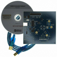
AD9913/PCBZ
Description
Eval Board
Manufacturer
Analog Devices Inc
Series
AgileRF™r
Datasheet
1.AD9913BCPZ.pdf
(32 pages)
Specifications of AD9913/PCBZ
Silicon Manufacturer
Analog Devices
Application Sub Type
Direct Digital Synthesizer
Kit Application Type
Clock & Timing
Silicon Core Number
AD9913
Kit Contents
Board
Tool / Board Applications
D/A Converter
Main Purpose
Timing, Direct Digital Synthesis (DDS)
Embedded
No
Utilized Ic / Part
AD9913
Primary Attributes
10-Bit DAC, 32-Bit Tuning Word Width
Secondary Attributes
250MHz, Graphical User Interface
Lead Free Status / RoHS Status
Lead free / RoHS Compliant


AD9913
Control Function Register 2 (CFR2)
Address 0x01; 2 bytes are assigned to this register.
Table 11. Bit Descriptions for CFR2
Bit(s)
15
14:9
8
7
6
5
4
3
2
1
0
DAC Control Register
Address 0x02; 4 bytes are assigned to this register.
Table 12. Bit Descriptions for DAC Control Register
Bit(s)
15:14, 10
9:0
31:16,13:11
Frequency Tuning Word Register (FTW)
Address 0x03, 4 bytes are assigned to this register.
Table 13. Bit Descriptions for FTW Register
Bit(s)
31:0
Phase Offset Word Register (POW)
Address 0x04, 2 bytes are assigned to this register.
Table 14. Bit Descriptions for POW Register
Bit(s)
15:14
13:0
Bit Name
PLL Output Div by 2
PLL Multiplication Factor
Open
CMOS Clock Mode
Crystal Clock Mode
PLL Power-Down
PLL LO Range
PLL Input Div by 2
VCO2 Sel
PLL Reset
PLL Lock
Bit Name
Open
FSC
Reserved
Bit Name
Frequency Tuning Word
Phase Offset Word
Bit Name
Open
Description
See Table 7 for details on multiplication factor configuration.
Leave this bit at the default state.
See Table 6 for directions on programming this bit.
See Table 6 for directions on programming this bit.
0 = PLL is active
1 = PLL is inactive and in its lowest power state
0 = use this setting for PLL if the PLL reference frequency is >5 MHz.
1 = use this setting for PLL if the PLL reference frequency is <5 MHz.
0 = the PLL reference frequency = the REF_CLK input frequency.
1 = the PLL reference frequency = ½ the REF_CLK input frequency.
0 = use this setting for VCO frequencies below 100 MHz and/or to optimize for power rather
than performance.
1 = use this setting to optimize for performance; this setting results in slightly higher power
consumption. Note: When setting this bit, an IO_UPDATE must occur within 40 μs of the PLL
power-down bit (CFR2 [5]) going low.
0 = the PLL logic is reset and non-operational until this bit is set.
1 = the PLL logic operates normally.
This read-only bit is set when the REF_CLK PLL is locked.
Description
Leave these bits at their default state.
This 10-bit number controls the full-scale output current of the DAC.
Leave these bits at their default state.
Description
32-bit frequency tuning word.
Description
Leave these bits at their default state.
14-bit phase offset word.
Rev. A | Page 30 of 32
Related parts for AD9913/PCBZ
Image
Part Number
Description
Manufacturer
Datasheet
Request
R


Part Number:
Description:
±1.7g Dual-Axis IMEMS Accelerometer Evaluation Board
Manufacturer:
Analog Devices Inc
Datasheet:

Part Number:
Description:
Inertial Sensor Evaluation System
Manufacturer:
Analog Devices Inc
Datasheet:
Part Number:
Description:
Manufacturer:
Analog Devices Inc
Datasheet:
Part Number:
Description:
Manufacturer:
Analog Devices Inc
Datasheet:
Part Number:
Description:
Manufacturer:
Analog Devices Inc
Datasheet:
Part Number:
Description:
Manufacturer:
Analog Devices Inc
Datasheet:
Part Number:
Description:
Manufacturer:
Analog Devices Inc
Datasheet:
Part Number:
Description:
Manufacturer:
Analog Devices Inc
Datasheet:
Part Number:
Description:
Manufacturer:
Analog Devices Inc
Datasheet:
Part Number:
Description:
Manufacturer:
Analog Devices Inc
Datasheet:
Part Number:
Description:
Manufacturer:
Analog Devices Inc
Datasheet:
Part Number:
Description:
Manufacturer:
Analog Devices Inc
Datasheet: