AD9913/PCBZ Analog Devices Inc, AD9913/PCBZ Datasheet - Page 17
AD9913/PCBZ
Manufacturer Part Number
AD9913/PCBZ
Description
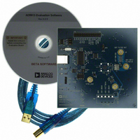
Eval Board
Manufacturer
Analog Devices Inc
Series
AgileRF™r
Datasheet
1.AD9913BCPZ.pdf
(32 pages)
Specifications of AD9913/PCBZ
Silicon Manufacturer
Analog Devices
Application Sub Type
Direct Digital Synthesizer
Kit Application Type
Clock & Timing
Silicon Core Number
AD9913
Kit Contents
Board
Tool / Board Applications
D/A Converter
Main Purpose
Timing, Direct Digital Synthesis (DDS)
Embedded
No
Utilized Ic / Part
AD9913
Primary Attributes
10-Bit DAC, 32-Bit Tuning Word Width
Secondary Attributes
250MHz, Graphical User Interface
Lead Free Status / RoHS Status
Lead free / RoHS Compliant


PS[0]
PS[1]
PS[0]
PS[1]
PS[0]
PS[1]
E0
S0
E0
S0
E0
S0
Figure 24. Display of Bidirectional Ramp Capability
NO-DWELL BIT = x
BIDIRECTIONAL MODE (LEVEL TRIGGERED)
BIDIRECTIONAL MODE (EDGE TRIGGERED)
NO-DWELL BIT = 0
NO-DWELL BIT = 1
Using the External Profile Pins
Rev. A | Page 17 of 32
Clear Functions
The AD9913 allows for a programmable continuous zeroing of
the sweep logic and the phase accumulator as well as clear-and-
release, or automatic zeroing function. Each feature is
individually controlled via bits in the control registers.
Continuous Clear Bits
The continuous clear bits are simply static control signals that
hold the respective accumulator (and associated logic) at zero
for the entire time the bit is active.
Clear-and-Release Function
The auto clear auxiliary accumulator bit, when active, clears and
releases the auxiliary accumulator upon receiving an
I/O_UPDATE or change in profile bits.
The auto clear phase accumulator, when active, clears and
releases the phase accumulator upon receiving a I/O_UPDATE
or a change in profile bits.
The automatic clearing function is repeated for every
subsequent I/O_UPDATE or change in profile bits until the
control bit is cleared.
These bits are programmed independently and do not have to
be active at the same time. For example, one accumulator may
be using the clear and release function while the other is
continuously cleared.
Figure 25. Combination of Sweep Modes Using the External Profile Pins
PS[0]
PS[1]
E0
S0
COMBINATION OF MODES (EDGE TRIGGERED)
RAMP UP
MODE
RAMP DOWN
MODE
BIDIRECTIONAL
MODE
RAMP UP
MODE
AD9913
Related parts for AD9913/PCBZ
Image
Part Number
Description
Manufacturer
Datasheet
Request
R


Part Number:
Description:
±1.7g Dual-Axis IMEMS Accelerometer Evaluation Board
Manufacturer:
Analog Devices Inc
Datasheet:

Part Number:
Description:
Inertial Sensor Evaluation System
Manufacturer:
Analog Devices Inc
Datasheet:
Part Number:
Description:
Manufacturer:
Analog Devices Inc
Datasheet:
Part Number:
Description:
Manufacturer:
Analog Devices Inc
Datasheet:
Part Number:
Description:
Manufacturer:
Analog Devices Inc
Datasheet:
Part Number:
Description:
Manufacturer:
Analog Devices Inc
Datasheet:
Part Number:
Description:
Manufacturer:
Analog Devices Inc
Datasheet:
Part Number:
Description:
Manufacturer:
Analog Devices Inc
Datasheet:
Part Number:
Description:
Manufacturer:
Analog Devices Inc
Datasheet:
Part Number:
Description:
Manufacturer:
Analog Devices Inc
Datasheet:
Part Number:
Description:
Manufacturer:
Analog Devices Inc
Datasheet:
Part Number:
Description:
Manufacturer:
Analog Devices Inc
Datasheet: