ADC-24 PICO TECHNOLOGY, ADC-24 Datasheet - Page 46
ADC-24
Manufacturer Part Number
ADC-24
Description
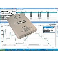
DATALOGGER, HI-RES
Manufacturer
PICO TECHNOLOGY
Datasheet
1.ADC-20.pdf
(51 pages)
Specifications of ADC-24
Connector Type
D25 Female
Interface
USB 1.1 (USB 2.0 Compatible)
No. Of Channels
16
Power Supply
From USB
Resolution
24 Bits
Interface Type
USB 1.1 (USB 2.0 Compatible)
Rohs Compliant
NA
Lead Free Status / RoHS Status
na


43
6
adc20.en
Glossary
Asynchronous. In asynchronous data collection, your application requests data from
the driver, and the driver immediately returns without blocking the application. The
application must then poll a status function until the data is ready.
Common-mode rejection ratio. The ratio by which the data logger attenuates a
common-mode voltage (see below). It is defined as:
where CMRR(dB) is the common-mode rejection ratio in decibels, Vin is the common-
mode voltage present at the input, and Vmeas is the common-mode voltage visible in
the measured data.
Common mode voltage. A differential signal fed into the data logger consists of a
positive input (Vp) and a negative input (Vn), and the logger measures the difference
(Vdiff = Vp - Vn) between the two inputs. This means that any offset in ground
potential between the signal source and the data logger adds a constant voltage,
called the common mode voltage (Vcm), to both inputs equally, so ideally it does not
affect Vdiff. In practice, however, the data logger cannot make an accurate
measurement if Vcm is too large, and even small values of Vcm may affect the
reading slightly.
Data logger. A measuring instrument that monitors one or more analog signals,
samples them at pre-programmed intervals, then accurately converts the samples to
digital data and stores them in memory. The ADC-20 and ADC-24 use your PC for
storage and display.
DLL. Dynamic Link Library. A DLL is a file containing a collection of Windows
functions designed to perform a specific class of operations.
Driver. A driver is a computer program that acts as an interface, generally between a
hardware component and a computer system, the hardware in this case being the
data logger.
EMC. Electromagnetic compatibility. The ability of a device to operate in proximity
with other devices without causing or suffering undue interference from
electromagnetic fields or conducted electrical noise.
Gain error. Gain error is the worst deviation of a measurement from the true value,
measured over the whole input range and expressed as a percentage.
Galvanic isolation. A barrier between two parts of an electrical circuit that prevents
noise and voltage offsets in one part from affecting the other part.
Input impedance. This is the impedance of the input channel of the data logger.
Impedance is the ratio of the voltage across the input to the current flowing through
it, and at low frequencies can be considered as a pure resistance. The larger the
impedance, the more accurate the measurement.
Input voltage range. The input voltage range is the range of voltages that an analog
channel can convert without an overload error. The maximum input voltage range of
the ADC-20 and ADC-24 is therefore -2.5 V to +2.5V. Furthermore, you should not
inject voltages outside the range -5 V to +5 V, as this can cause measurement errors
on all channels. You will not damage the unit unless you exceed the overvoltage
protection voltage range.
CMRR(dB) = 20 log10 (Vin/Vmeas),
Copyright © 2005-2010 Pico Technology Ltd. All rights reserved.
Glossary
Related parts for ADC-24
Image
Part Number
Description
Manufacturer
Datasheet
Request
R

Part Number:
Description:
CONVERTER, A/D, 16 BIT
Manufacturer:
PICO TECHNOLOGY
Datasheet:

Part Number:
Description:
DATALOGGER, HI-RES
Manufacturer:
PICO TECHNOLOGY
Datasheet:

Part Number:
Description:
Type-K Thermocouple Probe
Manufacturer:
PICO TECHNOLOGY

Part Number:
Description:
Type-K Thermocouple Probe
Manufacturer:
PICO TECHNOLOGY

Part Number:
Description:
Type-K Thermocouple Insertion Probe
Manufacturer:
PICO TECHNOLOGY

Part Number:
Description:
Type-K Thermocouple Air Probe
Manufacturer:
PICO TECHNOLOGY
Part Number:
Description:
Type-K Thermocouple Probe
Manufacturer:
PICO TECHNOLOGY
Part Number:
Description:
Type-K Thermocouple Probe
Manufacturer:
PICO TECHNOLOGY
Part Number:
Description:
Type-K Thermocouple Probe
Manufacturer:
PICO TECHNOLOGY
Part Number:
Description:
Type-K Thermocouple Probe
Manufacturer:
PICO TECHNOLOGY

Part Number:
Description:
PROBE, PT100, INSERTION
Manufacturer:
PICO TECHNOLOGY
Datasheet:
Part Number:
Description:
PROBE, PT100, AIR, FAST RESPONSE
Manufacturer:
PICO TECHNOLOGY
Datasheet:
Part Number:
Description:
PROBE, PT100, GENERAL PURPOSE
Manufacturer:
PICO TECHNOLOGY
Datasheet: