ADC-24 PICO TECHNOLOGY, ADC-24 Datasheet - Page 37
ADC-24
Manufacturer Part Number
ADC-24
Description
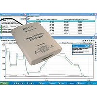
DATALOGGER, HI-RES
Manufacturer
PICO TECHNOLOGY
Datasheet
1.ADC-20.pdf
(51 pages)
Specifications of ADC-24
Connector Type
D25 Female
Interface
USB 1.1 (USB 2.0 Compatible)
No. Of Channels
16
Power Supply
From USB
Resolution
24 Bits
Interface Type
USB 1.1 (USB 2.0 Compatible)
Rohs Compliant
NA
Lead Free Status / RoHS Status
na


ADC-20/ADC-24 User's Guide
Copyright © 2005-2010 Pico Technology Ltd. All rights reserved.
Examples:
Example bit patterns for
The above is a selection of the 16 different options available for the
parameter. When a digital channel has been selected as an output, it can then be set
on or off with the
to represent the different digital channels.
The default setting for the digital channels is "output, off".
Decimal Bit
1
10
12
13
To set digital channels 1 and 2 to input and digital channels 3 and 4 to output:
directionOut =
HRDL_DIGITAL_IO_CHANNEL_4 (8) + HRDL_DIGITAL_IO_CHANNEL_3 (4) = 12
To set digital channel 4 high and digital channel 3 low:
digitalOutPinState = HRDL_DIGITAL_IO_CHANNEL_4 (8) = 8
To set only digital channel 3 high:
digitalOutPinState = HRDL_DIGITAL_IO_CHANNEL_3 (4) = 4
To turn both digital channels 3 and 4 on:
digitalOutPinState =
HRDL_DIGITAL_IO_CHANNEL_4 (8) + HRDL_DIGITAL_IO_CHANNEL_3 (4) = 12
Pattern
0001
1010
1100
1101
digitalOutputPinState
Digital
Channel 4
Input
Output
Output
Output
directionOut
Digital
Channel 3
Input
Input
Output
Output
parameter:
parameter, again using binary bit patterns
Digital
Channel 2
Input
Output
Input
Input
Digital
Channel 1
Output
Input
Input
Output
directionOut
adc20.en
34
Related parts for ADC-24
Image
Part Number
Description
Manufacturer
Datasheet
Request
R

Part Number:
Description:
CONVERTER, A/D, 16 BIT
Manufacturer:
PICO TECHNOLOGY
Datasheet:

Part Number:
Description:
DATALOGGER, HI-RES
Manufacturer:
PICO TECHNOLOGY
Datasheet:

Part Number:
Description:
Type-K Thermocouple Probe
Manufacturer:
PICO TECHNOLOGY

Part Number:
Description:
Type-K Thermocouple Probe
Manufacturer:
PICO TECHNOLOGY

Part Number:
Description:
Type-K Thermocouple Insertion Probe
Manufacturer:
PICO TECHNOLOGY

Part Number:
Description:
Type-K Thermocouple Air Probe
Manufacturer:
PICO TECHNOLOGY
Part Number:
Description:
Type-K Thermocouple Probe
Manufacturer:
PICO TECHNOLOGY
Part Number:
Description:
Type-K Thermocouple Probe
Manufacturer:
PICO TECHNOLOGY
Part Number:
Description:
Type-K Thermocouple Probe
Manufacturer:
PICO TECHNOLOGY
Part Number:
Description:
Type-K Thermocouple Probe
Manufacturer:
PICO TECHNOLOGY

Part Number:
Description:
PROBE, PT100, INSERTION
Manufacturer:
PICO TECHNOLOGY
Datasheet:
Part Number:
Description:
PROBE, PT100, AIR, FAST RESPONSE
Manufacturer:
PICO TECHNOLOGY
Datasheet:
Part Number:
Description:
PROBE, PT100, GENERAL PURPOSE
Manufacturer:
PICO TECHNOLOGY
Datasheet: