PD3-110-42-232 TRINAMIC, PD3-110-42-232 Datasheet - Page 10
PD3-110-42-232
Manufacturer Part Number
PD3-110-42-232
Description
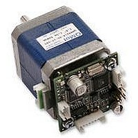
STEPPER MOTOR, PANDRIV, 42MM, 0.50NM
Manufacturer
TRINAMIC
Datasheet
1.PD1-110-42-232.pdf
(17 pages)
Specifications of PD3-110-42-232
Torque Max
0.49N-m
Current Rating
1A
No. Of Phases
2
External Depth
42mm
External Length / Height
49.5mm
External Width
42mm
Holding Torque
0.50N-m
Steps Per Revolution
RoHS Compliant
Coil Type
Bipolar
Svhc
No SVHC (15-Dec-2010)
Rohs Compliant
Yes


to the TMC428 via SPI by the microcontroller. Calculation of ramps and speed profiles are done internally by
hardware based on the target motion parameters.
5.1.4 TMC246 Motor Driver
The stepper motor driver used on the TMCM-110 module is the TMC246 chip. This driver is very
dependable, because it provides a variety of protection and diagnostic features, which even can be read out
by the user software. Its 16x up to 32x microstepping gives a quiet and precise motor operation. As the
power dissipation of the TMC246 chips is very low no heat sink or cooling fan is needed. The temperature of
the chips does not get too high easily. The coils will be switched off automatically when the temperature or
the current exceeds the limits and automatically switched on again when the values are within the limits
again.
5.2 Power Supply
The TMCM-110-42 is equipped with a linear voltage regulator that generates the 5V supply voltage for the
digital components of the module from the motor power supply. So only one supply voltage is needed for the
module. The power supply voltage can be 12..30 V DC. A higher voltage gives higher motor dynamics.
Please note that there is no protection against reverse polarity or too high voltage.
When using supply voltages near the upper limit of 34V, a regulated power supply becomes a must. Please
ensure, that enough power filtering capacitors are provided in the system (470µF or more recommended per
motor), in order to absorb mechanical energy fed back by the motor in stalling conditions.
The power supply should be designed in a way, that it supplies the nominal motor voltage at the desired
maximum motor power. In no case shall the supply value exceed the upper / lower voltage limit. To ensure
reliable operation of the unit, the power supply has to have a sufficient output capacitor and the supply
cables should have a low resistance, so that the chopper operation does not lead to an increased power
supply ripple directly at the unit. Power supply ripple due to the chopper operation should be kept at a
maximum of a few 100mV. This also is important in order to make the users application compatible to any
applicable EMC guidelines.
Therefore we recommend to
5.3 Communication Interface
The communication between the host and the module takes place via its host interface. This can be either
RS232, RS485, IIC or CAN. Please note that the TMCM-110-42 module can only be equipped with one of
these interfaces. Communication with the TMCM-110-42 module is done using TMCL commands. The
interface the module is equipped with is ready-to-use, so there are no external drivers or level shifters
necessary.
Please see chapter 3.3.1 for the pin assignments of the interfaces.
To use the TMCL IDE with CAN interface either the Trinamic CANnes card or the Trinamic USB2X interface
is needed. To use the IIC interface with the TMCL IDE the Trinamic USB2X interface is needed.
5.4 Reference Switches
Two digital reference / stop switch inputs are provided (StopL= stop left and StopR = stop right). They are
used as an absolute position reference for homing and to set a hardware limit for the motion range. The
inputs have internal pullup resistors. Either opto-switches or mechanical switched with normally closed
contact can be used. The 5V output can be used as an supply for opto-switches.
Copyright © 2005, TRINAMIC Motion Control GmbH & Co. KG
a) keep power supply cables as short as possible
b) use large diameter for power supply cables
c) if the distance to the power supply is large (i.e. more than 2 - 6m), use a robust 470µF or larger
additional filtering capacitor located near to the motor driver unit.
TMCM-110-42 Manual
10
Related parts for PD3-110-42-232
Image
Part Number
Description
Manufacturer
Datasheet
Request
R

Part Number:
Description:
42mm / NEMA17 Stepper Motor with Controller / Driver and Serial Interface
Manufacturer:
TRINAMIC [TRINAMIC Motion Control GmbH & Co. KG.]
Datasheet:

Part Number:
Description:
STEPPER MOTOR, PANDRIV, 42MM, 0.50NM
Manufacturer:
TRINAMIC
Datasheet:
Part Number:
Description:
STEPPER MOTOR, PANDRIV, 42MM, 0.50NM
Manufacturer:
TRINAMIC
Datasheet:
Part Number:
Description:
57mm/NEMA23 or 60mm/NEMA24 Stepper Motor with Controller/Driver with Encoder and Serial Interface
Manufacturer:
TRINAMIC [TRINAMIC Motion Control GmbH & Co. KG.]
Datasheet:
Part Number:
Description:
60mm/NEMA24 Stepper Motor with Controller/Driver, with Encoder and Serial Interface
Manufacturer:
TRINAMIC [TRINAMIC Motion Control GmbH & Co. KG.]
Datasheet:
Part Number:
Description:
57mm / NEMA23 Stepper Motor with Controller / Driver and Serial Interface
Manufacturer:
TRINAMIC [TRINAMIC Motion Control GmbH & Co. KG.]
Datasheet:
Part Number:
Description:
42mm/NEMA17 Stepper Motor with Controller/Driver, Encoderand Serial Interface
Manufacturer:
TRINAMIC [TRINAMIC Motion Control GmbH & Co. KG.]
Datasheet:
Part Number:
Description:
42mm/NEMA17 High Performance BLDC Motor with Controller/Driver and Serial Interface
Manufacturer:
TRINAMIC [TRINAMIC Motion Control GmbH & Co. KG.]
Datasheet:
Part Number:
Description:
57mm diameter BLDC Encoder Motor with Controller/Driver and Serial Interface
Manufacturer:
TRINAMIC [TRINAMIC Motion Control GmbH & Co. KG.]
Datasheet:

Part Number:
Description:
2.54mm Pitch Power Board To Boardconnector
Manufacturer:
DDK Ltd.
Datasheet:
Part Number:
Description:
28mm Nema11 Stepper Motor With Controller Driver Serial Interface
Manufacturer:
ETC-unknow
Datasheet:
Part Number:
Description:
3-way Wilkinson Power Divider
Manufacturer:
Marki Microwave
Datasheet:
Part Number:
Description:
3-way Wilkinson Power Divider
Manufacturer:
Marki Microwave
Datasheet: