TMC SIXPACK 2 TRINAMIC, TMC SIXPACK 2 Datasheet - Page 12
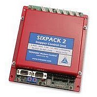
TMC SIXPACK 2
Manufacturer Part Number
TMC SIXPACK 2
Description
CONTROLLER, STEPPER MOTOR, AMPLIF
Manufacturer
TRINAMIC
Datasheet
1.TMC_SIXPACK_2.pdf
(48 pages)
Specifications of TMC SIXPACK 2
Supply Voltage Range
15Vdc To 48Vdc
No. Of Phases
Two
Output Current
1.4A
Approval Bodies
CE
Current Limit Max
1.4A
Current Limit Min
300mA
External Depth
35mm
External Length / Height
180mm
Svhc
No SVHC (15-Dec-2010)
Rohs Compliant
Yes
Lead Free Status / RoHS Status
Lead free / RoHS Compliant


SIXpack 2 – manual (V1.01 / May 5
5.2.8 Adjusting chopper mode
The SIXpack 2 supports “Mixed Decay” which provides reduced motor resonance at medium velocities
and improved microstep exactness. This mode can be switched off by the DIP-switches if desired.
5.3 Connections
Initial operation of the SIXpack 2 is possible after installing current supply and serial interface.
5.3.1 Current supply
Any power supply unit with an output voltage of 15-48V may be used. The required current is conform to
the usage and quantity of motors. The connector is labeled POWER. Be aware that the polarity is correct
and make sure that your supply voltage never exceeds the absolute maximum rating.
With an appropriate current supply the LEDs “+5V” and “+24V” light up and the 7-segment-display shows
zero. If the display shows “8”, “C” or “F”, or the unit resets continuously, an internal defect has been
detected. When continuous resets occur, the Flash memory could be erased. You can try to swap flash
with an other device.
5.3.2 Serial interface
The RS232 interface is connected via a null modem cable with one serial interface of the PC.
5.3.3 Motor connectors
CAUTION: Connecting or disconnecting while power on may damage the motor drivers
of the SIXpack 2.
The function “Driver enable” (refer to 5.2.6) provides the possibility to disconnect motors while the
modules power is on. Thereby all actual settings are retained.
The motors are connected with the 8 pin connectors. The pinning of the connectors are as follows:
(motor 1, 3 and
(motor 2, 4 and
Mixed decay
Mixed decay
Mixed decay
(all motors)
Chopper
Scheme
5)
6)
DIP-switch position
MD_135
MD_246
MD_135
MD_246
MD_135
MD_246
ON
ON
ON
Table 5.3: Adjusting chopper mode
OFF
OFF
OFF
th
, 2006) 12
Mixed decay for all motors
Mixed decay for motor 1, 3 and 5
Mixed decay for motor 2, 4 and 6
description
Related parts for TMC SIXPACK 2
Image
Part Number
Description
Manufacturer
Datasheet
Request
R

Part Number:
Description:
Alarm, Piezoelectric, 75 dBA to 95 dBA @ 2 Ft., Medium Loud Continuous, 30-120VAC
Manufacturer:
Floyd Bell Inc.
Part Number:
Description:
Alarm, Piezoelectric, 75 dBA to 95 dBA @ 2 Ft., Medium Loud Continuous, 9-48VDC
Manufacturer:
Floyd Bell Inc.
Part Number:
Description:
57mm/NEMA23 or 60mm/NEMA24 Stepper Motor with Controller/Driver with Encoder and Serial Interface
Manufacturer:
TRINAMIC [TRINAMIC Motion Control GmbH & Co. KG.]
Datasheet:
Part Number:
Description:
60mm/NEMA24 Stepper Motor with Controller/Driver, with Encoder and Serial Interface
Manufacturer:
TRINAMIC [TRINAMIC Motion Control GmbH & Co. KG.]
Datasheet:
Part Number:
Description:
42mm/NEMA17 Stepper Motor with Controller/Driver, Encoderand Serial Interface
Manufacturer:
TRINAMIC [TRINAMIC Motion Control GmbH & Co. KG.]
Datasheet:

Part Number:
Description:
42mm/NEMA17 High Performance BLDC Motor with Controller/Driver and Serial Interface
Manufacturer:
TRINAMIC [TRINAMIC Motion Control GmbH & Co. KG.]
Datasheet:
Part Number:
Description:
57mm diameter BLDC Encoder Motor with Controller/Driver and Serial Interface
Manufacturer:
TRINAMIC [TRINAMIC Motion Control GmbH & Co. KG.]
Datasheet:
Part Number:
Description:
57mm / NEMA23 Stepper Motor with Controller / Driver and Serial Interface
Manufacturer:
TRINAMIC [TRINAMIC Motion Control GmbH & Co. KG.]
Datasheet:
Part Number:
Description:
42mm / NEMA17 Stepper Motor with Controller / Driver and Serial Interface
Manufacturer:
TRINAMIC [TRINAMIC Motion Control GmbH & Co. KG.]
Datasheet:
