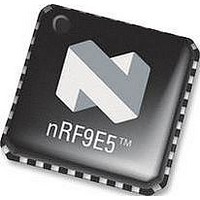
NRF9E5 NORDIC SEMICONDUCTOR, NRF9E5 Datasheet - Page 59

NRF9E5
Manufacturer Part Number
NRF9E5
Description
TRX, 430-928MHZ, MCU/ADC/PWM, SMD
Manufacturer
NORDIC SEMICONDUCTOR
Datasheet
1.NRF9E5.pdf
(108 pages)
Specifications of NRF9E5
Receiving Current
12.5mA
Transmitting Current
30mA
Data Rate
50Kbps
Frequency Range
430MHz To 928MHz
Modulation Type
GFSK
Rf Ic Case Style
QFN
No. Of Pins
32
Supply Voltage Range
1.9V To
Lead Free Status / RoHS Status
Lead free / RoHS Compliant
Available stocks
Company
Part Number
Manufacturer
Quantity
Price
Company:
Part Number:
NRF9E5C
Manufacturer:
NORDIC
Quantity:
5 000
Part Number:
NRF9E5C
Manufacturer:
NORDIC
Quantity:
20 000
PRODUCT SPECIFICATION
nRF9E5 Single Chip Transceiver with Embedded Microcontroller and ADC
17 POWER SAVING MODES
nRF9E5 provides the two industry standard 8051 power saving modes: idle mode and
stop mode. To Achieve more power saving several additional power-down modes are
provided, where both oscillator and internal power regulators may be turned off.
The bits that control entry into idle and stop modes are in the PCON register at SFR
address 0x87, listed in Table 49. The bits that control entry into power down mode are in
the CK_CTRL register at SFR address 0xB6, listed in Table 51.
17.1 Standard 8051 Power Saving Modes
17.1.1 Idle Mode
An instruction that sets the IDLE bit (PCON.0) causes the nRF9E5 to enter idle mode
when that instruction completes. In idle mode, CPU processing is suspended and internal
registers and memory maintain their current data. However, unlike the standard 8051,
the CPU clock is not disabled internally, thus not much power is saved.
There are two ways to exit idle mode: activate any enabled interrupt or watchdog reset.
Activation of any enabled interrupt causes the hardware to clear the IDLE bit and
terminate idle mode. The CPU executes the ISR associated with the received interrupt.
The RETI instruction at the end of the ISR returns the CPU to the instruction following
the one that put the nRF9E5 into idle mode. A watchdog reset causes the nRF9E5 to exit
idle mode, reset internal registers, execute its reset sequence and begin program
execution at the standard reset vector address 0x0000.
17.1.2 Stop Mode
An instruction that sets the STOP bit (PCON.1) causes the nRF9E5 to enter stop mode
when that instruction completes. Stop mode is identical to idle mode, except that the
only way to exit stop mode is by watchdog reset Since there is little power saving, stop
mode is not recommended, as it is more efficient to use power down mode.
Main office: Nordic Semiconductor ASA - Vestre Rosten 81, N-7075 Tiller, Norway -Phone +4772898900 - Fax +4772898989
Revision: 1.3
Bit
PCON.7
PCON.6–4
PCON.3
PCON.2
PCON.1
PCON.0
Function
SMOD – Serial Port baud-rate doubler enable. When SMOD = 1, the baud rate for
Serial Port is doubled.
Reserved.
GF1 – General purpose flag 1. General purpose flag for software control.
GF0 – General purpose flag 0. General purpose flag for software control.
STOP – Stop mode select. Setting the STOP bit places the nRF9E5 in stop mode.
IDLE – Idle mode select. Setting the IDLE bit places the nRF9E5 in idle mode.
Table 49 PCON Register – SFR 0x87.
Page 59 of 108
June 2006


