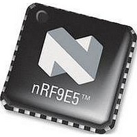
NRF9E5 NORDIC SEMICONDUCTOR, NRF9E5 Datasheet - Page 30

NRF9E5
Manufacturer Part Number
NRF9E5
Description
TRX, 430-928MHZ, MCU/ADC/PWM, SMD
Manufacturer
NORDIC SEMICONDUCTOR
Datasheet
1.NRF9E5.pdf
(108 pages)
Specifications of NRF9E5
Receiving Current
12.5mA
Transmitting Current
30mA
Data Rate
50Kbps
Frequency Range
430MHz To 928MHz
Modulation Type
GFSK
Rf Ic Case Style
QFN
No. Of Pins
32
Supply Voltage Range
1.9V To
Lead Free Status / RoHS Status
Lead free / RoHS Compliant
Available stocks
Company
Part Number
Manufacturer
Quantity
Price
Company:
Part Number:
NRF9E5C
Manufacturer:
NORDIC
Quantity:
5 000
Part Number:
NRF9E5C
Manufacturer:
NORDIC
Quantity:
20 000
PRODUCT SPECIFICATION
nRF9E5 Single Chip Transceiver with Embedded Microcontroller and ADC
10 AD CONVERTER SUBSYSTEM
10.1 AD Converter
The nRFE5 AD converter has 10 bit dynamic range and linearity when used at the
Nyquist rate. With lower signal frequencies and post filtering, up to 12 bits resolution is
possible. The reference for the AD converter is selectable between the AREF input and
an internal 1.22V bandgap reference.
The converter default SPI setting is 10 bits. For special requirements, the AD converter
can be configured to perform 6, 8, 10 or 12 bit conversions. The converter may also be
used in differential mode with AIN0 used as inverting input and one of the other 3
external inputs used as noninverting input.
Two
ADC_DATA_REG. AD converter status bit are available in the STATUS_REGISTER.
Registers are described in detail in chapter 11.
Selection of input channel is directly embedded in the START_ADC_CONV command,
alternatively it is set by CHSEL in the ADC_CONFIG_REG. Values of CHSEL from 0
to 3 would select AIN0 to AIN3 respectively. Setting CHSEL to [1xxx] will monitor the
nRF9E5 supply voltage by converting an internal input that is VDD/3 with the 1.22V
internal reference.
The AD conversion result is available as ADCDATA in ADC_DATA_REG at the end
of conversion. The data in ADC_DATA_REG is stored according to Table 19 with left
or right justified data selected by ADC_RL_JUST.
Overflow status is stored as ADC_RFLAG in the STATUS_REGISTER after each
conversion.
The complete subsystem is switched off by clearing bit ADC_PWR_UP.
Instructions for the AD converter are given in Table 21 on page 36.
Main office: Nordic Semiconductor ASA - Vestre Rosten 81, N-7075 Tiller, Norway -Phone +4772898900 - Fax +4772898989
Revision: 1.3
ADC_
RL_JUST
0
0
0
0
1
1
1
1
registers
ADC
_RESCTRL
00
01
10
11
00
01
10
11
Table 19 ADC_DATA_REGISTER justified data.
interface
# bit
6
8
10
12
6
8
10
12
the
Page 30 of 108
AD
ADC_DATA_REG[15:0]
High byte [15:8]
ADCDATA[5:0]
ADCDATA[7:0]
ADCDATA[9:0]
ADCDATA[11:0]
‘0’
converter,
ADCDATA[11:0]
ADCDATA[9:0]
ADC_CONFIG_REG
Low byte [7:0]
ADCDATA[7:0]
ADCDATA[5:0]
‘0’
June 2006
and


