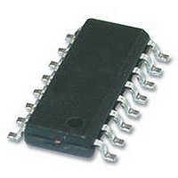
TEA1751LT/N1 NXP Semiconductors, TEA1751LT/N1 Datasheet - Page 9

TEA1751LT/N1
Manufacturer Part Number
TEA1751LT/N1
Description
AC-DC, PFC, FLYBACK, CNTRL, 16SOIC
Manufacturer
NXP Semiconductors
Datasheet
1.TEA1751LTN1518.pdf
(29 pages)
Specifications of TEA1751LT/N1
Input Voltage
276V
Output Current
1.2A
Output Voltage
11V
No. Of Outputs
2
Power Dissipation Pd
600mW
Voltage Regulator Case Style
SOIC
No. Of Pins
16
Operating Temperature Range
-40°C To
Supply Voltage Range
21V To 23V
Rohs Compliant
Yes
Lead Free Status / RoHS Status
Lead free / RoHS Compliant
Available stocks
Company
Part Number
Manufacturer
Quantity
Price
Company:
Part Number:
TEA1751LT/N1
Manufacturer:
SEIKO
Quantity:
55 000
Part Number:
TEA1751LT/N1
Manufacturer:
NXP/恩智浦
Quantity:
20 000
NXP Semiconductors
TEA1751T_LT_2
Product data sheet
7.2.3 Frequency limitation
7.2.4 Mains voltage compensation (VINSENSE pin)
7.2.5 Soft start-up (pin PFCSENSE)
To optimize the transformer and minimize switching losses, the switching frequency is
limited to f
limit, the system switches over to discontinuous conduction mode. Also here, the PFC
MOSFET is only switched on at a minimum voltage across the switch (valley switching).
The mathematical equation for the transfer function of a power factor corrector contains
the square of the mains input voltage. In a typical application this results in a low
bandwidth for low mains input voltages, while at high mains input voltages the Mains
Harmonic Reduction (MHR) requirements may be hard to meet.
To compensate for the mains input voltage influence, the TEA1751(L)T contains a
correction circuit. Via the VINSENSE pin the average input voltage is measured and the
information is fed to an internal compensation circuit. With this compensation it is possible
to keep the regulation loop bandwidth constant over the full mains input range, yielding a
fast transient response on load steps, while still complying with class-D MHR
requirements.
In a typical application, the bandwidth of the regulation loop is set by a resistor and two
capacitors on the PFCCOMP pin.
To prevent audible transformer noise at start-up or during hiccup, the transformer peak
current, I
inserting R
An internal current source charges the capacitor to V
voltage is limited to V
The start level and the time constant of the increasing primary current level can be
adjusted externally by changing the values of R
The charging current I
below 0.5 V (typ). If the voltage on pin PFCSENSE exceeds 0.5 V, the soft start current
source starts limiting current I
I
τsoftstart
start(soft)PFC
DM
sw(PFC)max
SS1
=
, is increased slowly by the soft start function. This can be achieved by
current source is switched off; see
3
and C
×
R
SS1
. If the frequency for quasi-resonant operation is above the f
SS1
Rev. 02 — 23 December 2009
start(soft)PFC
×
start(soft)PFC
C
between pin PFCSENSE and current sense resistor R
SS1
start(soft)PFC
.
flows as long as the voltage on pin PFCSENSE is
. As soon as the PFC starts switching, the
TEA1751T; TEA1751LT
Figure
SS1
and C
PFCSENSE
5.
GreenChip III SMPS control IC
SS1
.
= I
start(soft)PFC
© NXP B.V. 2009. All rights reserved.
× R
SENSE1
sw(PFC)max
SS1
. The
9 of 29
.


