NTE21128 NTE ELECTRONICS, NTE21128 Datasheet - Page 3
NTE21128
Manufacturer Part Number
NTE21128
Description
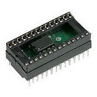
IC, EPROM, 128KBIT, 250NS, DIP-28
Manufacturer
NTE ELECTRONICS
Datasheet
1.NTE21128.pdf
(6 pages)
Specifications of NTE21128
Memory Type
EPROM - OTP
Memory Size
128Kbit
Memory Configuration
16K X 8
Access Time
250ns
Supply Voltage Range
4.75V To 5.25V
Memory Case Style
DIP
No. Of Pins
28


AC Characteristics (Program, Program Verify, and Program Inhibit Modes):
Note 3. Initial Program Pulse width tolerance is 1msec 5%.
Test Conditions:
Capacitance: (T
Device Operation:
A single 5V power supply is required in the read mode. All inputs are TTL levels except for V
Read Mode
The NTE21128 has the following two control functions: Chip Enable (E) is the power control used for
device selection and Output Enable (G) is the output control used to gate data to the output pins, inde-
pendent of device selection.
Address access time (t
outputs after the falling edge of G, assuming that E has been low and the addresses have been stable
for at least t
Standby Mode
The standby mode, reducing the maximum active power current from 85mA to 40mA, is achieved by
applying a TTL high signal to the E input. When in the standby mode, the outputs are in a high imped-
ance state, independent of the G input.
Address Setup Time
E Setup Time
Data Setup Time
Address Hold Time
E Setup Time
Data Hold Time
Chip Enable to Output Float Delay
Data Valid from E
Program Pulse Width (Note 3)
V
Input Capacitance
Output Capacitance
PP
Setup Time
Input Pulse Levels: 0.45V to 2.4V
Input Timing Reference Level: 0.8V and 2.0V
Output Timing Reference Level: 0.8V and 2.0V
Input Rise and Fall Times: 20ns
Parameter
AVQV
Parameter
(T
A
– t
= +25
A
= +25 C, f = 1MHz)
GLQV
AVQV
.
5 C, V
) is equal to the delay from E to output (t
Symbol
CC
t
t
t
OES
t
t
t
t
t
CES
t
t
PW
DS
AH
DH
OE
AS
DF
VS
Symbol
= +5V 5%, V
C
C
OUT
IN
Input Pulse Levels = 0.45V to 2.4V,
Input Timing Reference
Level = 0.8V and 2V,
Output Timing Reference
Level = 0.8V and 2V,
Level = 0.8V and 2V,
Input Rise and Fall Times: 20ns
V
V
IN
OUT
= 0V
= 0V
PP
Test Conditions
Test Conditions
= +21V 0.5V)
ELQV
). Data is available at the
Min
Min
45
2
2
2
0
2
2
0
–
2
–
–
Typ
Typ
50
–
–
–
–
–
–
–
–
–
4
8
Max Unit
Max Unit
130
150
55
14
–
–
–
–
–
–
–
8
PP
ms
pF
pF
ns
ns
.
s
s
s
s
s
s
s
Related parts for NTE21128
Image
Part Number
Description
Manufacturer
Datasheet
Request
R

Part Number:
Description:
TRANSISTOR,BJT,PNP,75V V(BR)CEO,1A I(C),TO-202
Manufacturer:
NTE ELECTRONICS
Datasheet:

Part Number:
Description:
Silicon Complementary Transistors High Power, Low Collector Saturation Voltage Power Output
Manufacturer:
NTE [NTE Electronics]
Datasheet:
Part Number:
Description:
IC, DRAM, 4KBIT, DIP-16
Manufacturer:
NTE ELECTRONICS
Datasheet:
Part Number:
Description:
IC, DRAM, 4KBIT, DIP-16
Manufacturer:
NTE ELECTRONICS
Datasheet:
Part Number:
Description:
IC, DRAM, 16KBIT, DIP-16
Manufacturer:
NTE ELECTRONICS
Datasheet:
Part Number:
Description:
IC, DRAM, 256KBIT, DIP-16
Manufacturer:
NTE ELECTRONICS
Datasheet:
Part Number:
Description:
IC, DRAM, 64KBIT, DIP-16
Manufacturer:
NTE ELECTRONICS
Datasheet:
Part Number:
Description:
IC, DRAM, 256KBIT, DIP-16
Manufacturer:
NTE ELECTRONICS
Datasheet:
Part Number:
Description:
IC, DRAM, 64KBIT, DIP-16
Manufacturer:
NTE ELECTRONICS
Datasheet:
Part Number:
Description:
IC, EPROM, 32KBIT, 300NS, DIP-24
Manufacturer:
NTE ELECTRONICS
Datasheet:

Part Number:
Description:
IC, 8BIT MPU, 1MHZ, DIP-28
Manufacturer:
NTE ELECTRONICS
Datasheet:
Part Number:
Description:
IC, EPROM, 32KBIT, 200NS, DIP-24
Manufacturer:
NTE ELECTRONICS
Datasheet:
Part Number:
Description:
IC, EPROM, 8KBIT, 450NS, DIP-24
Manufacturer:
NTE ELECTRONICS
Datasheet:

Part Number:
Description:
IC, 8BIT MPU, 1MHZ, DIP-40
Manufacturer:
NTE ELECTRONICS
Datasheet: