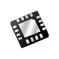
MMA5206WR2 Freescale Semiconductor, MMA5206WR2 Datasheet - Page 48

MMA5206WR2
Manufacturer Part Number
MMA5206WR2
Description
IC ACCELER 60G X-AXIS 16QFN
Manufacturer
Freescale Semiconductor
Datasheet
1.MMA5206WR2.pdf
(63 pages)
Specifications of MMA5206WR2
Sensing Axis
X
Acceleration
60 g
Sensitivity
0.125 g/LSB
Package / Case
QFN-16
Supply Voltage (max)
25 V
Supply Current
4 mA to 8 mA
Maximum Operating Temperature
+ 125 C
Minimum Operating Temperature
- 40 C
Mounting Style
SMD/SMT
Lead Free Status / RoHS Status
Lead free / RoHS Compliant
48
4.5.3
Mode”. In this mode, the 26 bit digital output from the DSP is clipped and scaled to a 16-bit word.
used to establish the 16-bit data word from the 26 bit DSP output.
Mode”, by setting the LATENCY bit to the desired operating mode. In Simultaneous Sampling Mode, the most recent interpolated
acceleration data sample is latched at t
polated acceleration data sample is latched at the time programmed in TIMESLOTA[9:0], relative to t
Pulse).
ative to t
at the time programmed in TIMESLOTB[9:0], relative to t
LOTB[9:0]. Identical data is transmitted in both Time slots, including the 10-Bit Resolution Raw Offset and Self-Test Data in Field
9, D27 though D31 if enabled.
Note: In the event that the programmed values in TIMESLOTA
MMA52xxWR
D25 D24 D23 D22 D21 D20 D19 D18 D17 D16 D15 D14 D13 D12 D11 D10 D9
Over Range
The device can be programmed to respond in 16-bit Resolution Mode by setting the TRANS_MD[1:0] bits to “16-bit Resolution
16-bit Data Word
16-Bit Resolution Mode can be programmed to operate in either “Simultaneous Sampling Mode”, or “Synchronous Sampling
The most significant 10 bits (D[21:12]) are truncated and transmitted starting at the time programmed in TIMESLOTA[9:0], rel-
When 16-Bit Resolution Mode is enabled, PSI5 Initialization data is transmitted in both TIMESLOTA[9:0] and TIMES-
transmitted in TIMESLOTB
TRIG
16-Bit Resolution Mode
. The 16-bit value is then clipped to ±480 counts, and the least significant 10 bits (D15:D6) are transmitted starting
D21 D20 D19 D18 D17 D16 D15 D14 D13 D12 D11 D10 D9
t
TIMESLOTA
Figure 39. 16-Bit Resolution Mode with Synchronous Sampling
[9:0]
t
TIMESLOTB
Signal
.
TRIG
Figure 38. 16-Bit Output Scaling Diagram
(rising edge of Sync Pulse). In Synchronous Sampling Mode, the most recent inter-
TRIG
.
[9:0]
and TIMESLOTB
≤t
LAT_INTERP
Noise
+ t
DATASETUP_16
[9:0]
D8
D8
result in a conflict, no data will be
D7
D7
Figure 38
D6
D6
TRIG
Freescale Semiconductor
D5
Margin
(rising edge of Sync
Using Rounding
shows the method
...
D2
D1
Sensors
D0


