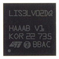
LIS3LV02DQ-TR STMicroelectronics, LIS3LV02DQ-TR Datasheet - Page 5

LIS3LV02DQ-TR
Manufacturer Part Number
LIS3LV02DQ-TR
Description
ACCELEROMETER TRPL AXIS 28QFPN
Manufacturer
STMicroelectronics
Specifications of LIS3LV02DQ-TR
Axis
X, Y, Z
Acceleration Range
±2g, 6g
Sensitivity
1024LSB/g, 340LSB/g
Voltage - Supply
2.16 V ~ 3.6 V
Output Type
Digital
Bandwidth
40Hz ~ 2.56kHz Selectable
Interface
I²C, SPI
Mounting Type
Surface Mount
Package / Case
28-QFN
Sensing Axis
X, Y, Z
Acceleration
2 g, 6 g
Digital Output - Number Of Bits
12 bit, 16 bit
Supply Voltage (max)
3.6 V
Supply Voltage (min)
2.16 V
Supply Current
0.6 mA
Maximum Operating Temperature
+ 85 C
Minimum Operating Temperature
- 40 C
Digital Output - Bus Interface
I2C, SPI
Package Type
QFN
Operating Supply Voltage (min)
2.16V
Operating Supply Voltage (typ)
2.5V
Operating Supply Voltage (max)
3.6V
Operating Temperature (min)
-40C
Operating Temperature (max)
85C
Operating Temperature Classification
Industrial
Product Depth (mm)
7mm
Product Height (mm)
1.75mm
Product Length (mm)
7mm
Mounting
Surface Mount
Pin Count
28
For Use With
497-6249 - BOARD EVAL ACCEL DGTL LIS3LV02DQ497-5069 - EVAL BOARD 3AXIS MEMS ACCELLRMTR
Lead Free Status / RoHS Status
Lead free / RoHS Compliant
Other names
497-6346-2
Available stocks
Company
Part Number
Manufacturer
Quantity
Price
Part Number:
LIS3LV02DQ-TR
Manufacturer:
ST
Quantity:
20 000
LIS3L02DQ
3.1 Terminology
3.1.1 Sensitivity
Sensitivity describes the gain of the sensor and can be determined e.g. by applying 1g acceleration to it.
As the sensor can measure DC accelerations this can be done easily by pointing the axis of interest to-
wards the center of the earth, note the output value, rotate the sensor by 180 degrees (point to the sky)
and note the output value again. By doing so, ±1g acceleration is applied to the sensor. Subtracting the
larger output value from the smaller one and divide the result by 2 leads to the actual sensitivity of the
sensor. This value changes very little over temperature (see sensitivity temperature change) and also very
little over time. The Sensitivity Tolerance describes the range of Sensitivities of a large population of sen-
sors.
3.1.2 Zero g level
Zero-g level (Offset) describes the deviation of an actual output signal from the ideal output signal if there
is no acceleration present. A sensor in a steady state on a horizontal surface will measure 0g in X axis
and 0g in Y axis whereas the Z axis will measure 1g. The output is ideally in the middle of the dynamic
range of the sensor (0000 0000 0000). A deviation from this value is called zero-g offset; the coding is
based two's complement. Offset is to some extend a result of stress to a precise MEMS sensor and there-
fore the offset can slightly change after mounting the sensor onto a printed circuit board or exposing it to
extensive mechanical stress. Offset changes little over temperature, see “Zero g level change vs. temper-
ature”. The Zero-g level of an individual sensor is very stable over lifetime. The Zero g level tolerance de-
scribes the range of zero g levels of a population of sensors.
3.1.3 Self Test
Self Test allows to test the mechanical and electrical part of the sensor. By applying a digital code via the
serial interface to the sensor an internal reference is switched to a certain area of the sensor and creates
a defined deflection of the moveable structure. The sensor will generate a defined signal and the interface
chip will perform the signal conditioning. If the output signal changes within the specified amplitude than
the sensor is working properly and the parameters of the interface chip are within tolerance. Self Test
changes linearly with power supply.
5/20


