3059Y-1-500LF Bourns Inc., 3059Y-1-500LF Datasheet - Page 34
3059Y-1-500LF
Manufacturer Part Number
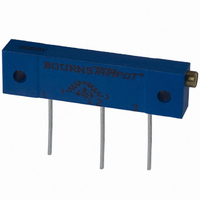
3059Y-1-500LF
Description
TRIMPOT 50 OHM 1.25"REC CER MT
Manufacturer
Bourns Inc.
Series
3059 - Sealedr
Specifications of 3059Y-1-500LF
Temperature Coefficient
±100ppm/°C
Resistance (ohms)
50
Termination Style
PC Pin
Power (watts)
1W
Tolerance
±10%
Number Of Turns
22
Adjustment Type
Side Adjustment
Resistive Material
Cermet
Mounting Type
Chassis Mount
Package / Case
Rectangular - 1.250" L x 0.190" W x 0.315" H (31.75mm x 4.83mm x 8.00mm)
Track Resistance
50ohm
No. Of Turns
22
Resistance Tolerance
± 10%
Power Rating
1W
Potentiometer Mounting
Through Hole
Resistance
50 Ohms
Operating Temperature Range
- 55 C to + 150 C
Element Type
Cermet
Dimensions
6.10 mm W x 31.75 mm L
Product
Trimmers
Taper
Linear
Rohs Compliant
Yes
Lead Free Status / RoHS Status
Lead free / RoHS Compliant
Lead Free Status / RoHS Status
Lead free / RoHS Compliant, Lead free / RoHS Compliant


Standard Resistance Range
Resistance Tolerance.....................±10 % std.
Absolute Minimum Resistance
Contact Resistance Variation
Resolution ...........................Essentially Infinite
Insulation Resistance.........................500 vdc.
Dielectric Strength
Adjustment Angle......................11 turns nom.
Power Rating (300 volts max.)
Temperature Range ............-65 °C to +150 °C
Temperature Coefficient.............±100 ppm/°C
Humidity ................MIL-STD 202 Method 106
Vibration ...............20 G TRS±1 %; VRS ±1 %
Shock .................100 G TRS ±1 %; VRS±1 %
Load Life ....@ 85 °C rated power 1,000 hours
TRS ......3 ohms or 3 % (whichever is greater)
Rotational Cycling ..........................200 cycles
TRS ......3 ohms or 3 % (whichever is greater)
Thermal Shock ..5 cycles, TRS±2 %; VRS±1 %
Mechanical Stop............................Wiper idles
Torque .....................................180 g-cm max.
Weight.........................Approximately 0.01 oz.
Marking..........................Manufacturer’s code,
Solderability ...Per MIL-STD-202, Method 208
Wiper ........................50 % (Actual TR) ±10 %
Flammability........................................UL94V0
Pushover Strength
Adjustment Tool .......................................H-91
Model
Style
Standard or Modified
Product Indicator
Resistance Code
Embossed Tape Designator
Consult factory for other available options.
* -2 has a treated stainless steel shaft
32
Electrical Characteristics
Environmental Characteristics
Physical Characteristics
How To Order
..........................................10 to 2 megohms
Sea Level..........................600 vac (1minute)
85 °C ..............................................0.25 watt
150 °C .................................................0 watt
J, G....................................................4.4 lbs.
W, X...................................................2.2 lbs.
.....................................1 % or 3 ohms max.
-FW5 = .070 ˝ ±.010 ˝ Shaft Extension
.......1 % or 2.0 ohms (whichever is greater)
-2* = Wave Solderable
-1 = IR Reflow (standard)
G = Style J, G: 1500 pcs./13 ˝ reel (standard)
G = Style J, G: 1500 pcs./13 ˝ reel (FW5)
E = Style J, G: 500 pcs./7 ˝ reel (standard)
Style W: 250 pcs./7 ˝ reel (standard)
Style X: 200 pcs./7 ˝ reel (standard)
Style W: 1000 pcs./13 ˝ reel (standard)
Style X: 850 pcs./13 ˝ reel (standard)
Style W, X: 600 pcs./13 ˝ reel (FW5)
resistance code and date code
(see standard resistance table)
TRS ±2 %; IR 10 megohms
3224 J - 1 - 502 E
100 megohms min.
3224 4 mm SMD Trimming Potentiometer
Features
I
I
I
Specifications are subject to change without notice.
†
Customers should verify actual device performance in
their specific applications.
(.060)
3224J Side Adjust
3224W Top Adjust
RoHS Directive 2002/95/EC Jan 27 2003 including Annex.
Product Dimensions
ADJUSTMENT SLOT
(.100)
1.52
(.155)
2.54
X
ADJUSTMENT SLOT
3.9
X
(.063)
(.020)
(.079)
Surface Mount 4 mm Square /
Multiturn / Cermet / Industrial /
Sealed
Sealed to withstand board wash
processing
Pick and place centering design, with
flush adjustment
(.022)
3
1
1.6
(.079)
0.56
.51
2.0
(.020)
DIA.
(.022)
(.051)
2.0
0.56
.51
(.102)
1.3
(.102)
2.6
TYP.
(.079)
2.6
TYP.
2.0
WIDE
DEEP
2 PLCS.
WIDE
DEEP
(.051)
(.157)
1.3
4.0
(.114)
2.9
(.138)
(.047)
(.100)
(.094)
3.5
2.54
2 PLCS.
1.2
2.4
(.047)
(.090)
(.060)
1.52
1.2
2.3
2
DIA.
(.008)
2
0.2
(.050)
1.3
(.181)
(.197)
(.035)
(.201)
5.0
4.6
(.047)
0.9
(.050)
5.1
(.209)
1.2
(.039)
2 PLCS.
1.3
5.3
1.0
(.031)
0.80
3 PLCS.
1
(.008)
3
0.2
2 PLCS.
(.034)
2 PLCS.
(.031)
REV 09/04
0.9
0.8
(.189)
(.189)
(.146)
(.051)
(.090)
4.8
3.7
4.8
2.3
1.3
I
I
I
I
(.060)
3224G Side Adjust
(.050)
(.031)
3224X Top Adjust
1.52
ADJUSTMENT SLOT
1.27
ADJUSTMENT SLOT
.80
(.052)
X
1.32
X
4 mm design meets EIA/EIAJ/IPC/VECI
SMD standard trimmer footprint
Low CRV - 1 %
DESC selected material drawing
#92021
RoHS compliant
processing information on lead free
surface mount trimmers
(.100)
(.079)
(.020)
2.54
(.022)
1
(.020)
(.022)
2.0
0.56
.51
DIA.
2 PLCS
0.56
.51
(.108)
TYP.
2.74
2 PLCS.
2 PLCS.
(.050)
1.27
WIDE
DEEP
(.074)
WIDE
(.205)
DEEP
1.9
5.2
TYP.
(.047)
(.094)
(.138)
1.2
(.090)
2.4
3.5
2.3
(.200)
(.051)
2
5.1
(.079)
1.3
(.047)
(.155)
†
2.0
1.2
3.9
- see page 155 for
2
DIMENSIONS: MM/(INCHES)
TOLERANCES: ±.25/(±.010)
EXCEPT WHERE NOTED
(.050)
1.3
(.008)
0.2
(.201)
(.039)
(.236)
(.180)
5.1
1.0
(.209)
4.57
6.0
(.008)
5.3
0.2
3 PLCS.
(.031)
0.80
1
3
(.024)
0.61
2 PLCS.
2 PLCS.
(.034)
(.154)
(.090)
3.91
0.9
(.189)
(.225)
2.3
(.189)
TYP.
(.100)
2.54
4.8
5.7
4.8
Related parts for 3059Y-1-500LF
Image
Part Number
Description
Manufacturer
Datasheet
Request
R

Part Number:
Description:
POT 500K OHM 1-1/4" RECT CERM MT
Manufacturer:
Bourns Inc.
Datasheet:
Part Number:
Description:
POT 100 OHM 1-1/4" RECT CERM MT
Manufacturer:
Bourns Inc.
Datasheet:
Part Number:
Description:
POT 10K OHM 1-1/4" RECT CERM MT
Manufacturer:
Bourns Inc.
Datasheet:
Part Number:
Description:
POT 100K OHM 1-1/4" RECT CERM MT
Manufacturer:
Bourns Inc.
Datasheet:
Part Number:
Description:
POT 1.0K OHM 1-1/4" RECT CERM MT
Manufacturer:
Bourns Inc.
Datasheet:
Part Number:
Description:
POT 50K OHM 1-1/4" RECT CERM MT
Manufacturer:
Bourns Inc.
Datasheet:
Part Number:
Description:
POT 2.0K OHM 1-1/4" RECT CERM MT
Manufacturer:
Bourns Inc.
Datasheet:
Part Number:
Description:
POT 200K OHM 1-1/4" RECT CERM MT
Manufacturer:
Bourns Inc.
Datasheet:
Part Number:
Description:
POT 20K OHM 1-1/4" RECT CERM MT
Manufacturer:
Bourns Inc.
Datasheet:
Part Number:
Description:
POT 1.0M OHM 1-1/4" RECT CERM MT
Manufacturer:
Bourns Inc.
Datasheet:

Part Number:
Description:
Manufacturer:
Bourns, Inc.
Datasheet:
Part Number:
Description:
11mm Potentiometer
Manufacturer:
Bourns, Inc.
Datasheet: