3059Y-1-500LF Bourns Inc., 3059Y-1-500LF Datasheet - Page 128
3059Y-1-500LF
Manufacturer Part Number
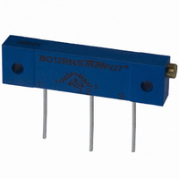
3059Y-1-500LF
Description
TRIMPOT 50 OHM 1.25"REC CER MT
Manufacturer
Bourns Inc.
Series
3059 - Sealedr
Specifications of 3059Y-1-500LF
Temperature Coefficient
±100ppm/°C
Resistance (ohms)
50
Termination Style
PC Pin
Power (watts)
1W
Tolerance
±10%
Number Of Turns
22
Adjustment Type
Side Adjustment
Resistive Material
Cermet
Mounting Type
Chassis Mount
Package / Case
Rectangular - 1.250" L x 0.190" W x 0.315" H (31.75mm x 4.83mm x 8.00mm)
Track Resistance
50ohm
No. Of Turns
22
Resistance Tolerance
± 10%
Power Rating
1W
Potentiometer Mounting
Through Hole
Resistance
50 Ohms
Operating Temperature Range
- 55 C to + 150 C
Element Type
Cermet
Dimensions
6.10 mm W x 31.75 mm L
Product
Trimmers
Taper
Linear
Rohs Compliant
Yes
Lead Free Status / RoHS Status
Lead free / RoHS Compliant
Lead Free Status / RoHS Status
Lead free / RoHS Compliant, Lead free / RoHS Compliant


Contact Rating
Contact Timing.......................Non-shorting
Contact Resistance................2 ohms max.
Insulation Resistance ...100 megohms min.
Dielectric Strength ........................250 VAC
Switch Type........................................SPDT
Operating Temperature Range
Storage Temperature Range
Seal Test ...........................85 °C Fluorinert*
Positions....................................................2
Adjustment Torque ..............1.8 N-cm max.
Stop Strength.......................2.5 N-cm min.
Pushover Strength (Z Style)
Weight.....................Approximately 0.2 gm.
Marking ...............................Manufacturer’s
Vibration ..............................................20 G
Shock ................................................100 G
Thermal Shock (5 cycles)..-55 °C to +125 °C
Humidity
Rotational Life
Max. Soldering Heat ...245 °C, 10 seconds
Packaging Options
Model
Terminal
Switch Type
Rotational Life
Optional Embossed Tape Designator
(For pin styles J, G, Z only –
omit for tube packaging)
126
Electrical Characteristics
General Characteristics
Mechanical Characteristics
Environmental Characteristics
How To Order
Maximum Current ...............100 mA max.
Maximum Voltage .............................16 V
Insulation Resistance....10 megohms min.
-051 ..........................................50 Cycles
-023 ......................................2000 Cycles
J & G...........................................500 pcs.
Z .................................................200 pcs.
H.........................................100 pcs./tube
...............................2 kilograms minimum
....................................-55 °C to +125 °C
....................................-55 °C to +125 °C
-051 = 50 Cycles
-023 = 2000 Cycles
-1 = SPDT
G = Gull Wing
H = Through-hole
Z = Right Angle
J = J-Hook
trademark, life code and date code
7814 J - 1 - 051 E
7814
SMD 4 mm Square Sealed Rotary Switch
Features
I
I
I
I
(.197)
DIMENSIONS: MM/(INCHES)
TOLERANCES: ±.2/(±.007) EXCEPT WHERE NOTED
7814J
J-Hook
7814G
Gull Wing
(.031 ± .004)
5.00
(.244)
Product Dimensions
3 PLCS.
0.80 ± 0.10
(.177)
(.093)
6.20
(.039)
4.50
2.35
1.00
(.051 ± .004)
2 PLCS.
1.30 ± 0.10
Single pole/double throw
Compatible with most surface mount
soldering processes
50 or 2000 cycle rotational life
Compatible with popular vacuum
pick-and-place equipment
(.177)
CW
4.50
051
CW
(.177)
(.197)
4.50
5.00
C
051
CCW
(.177)
7A
4.50
C
CCW
(.051 ± .004)
1.30 ± 0.10
7A
X
X
(.031 ± .004)
0.80 ± 0.10
ADJUSTMENT
SLOT
(.096)
(.020)
(.022)
2.45
2 PLCS.
(.093)
0.51
0.55
2.35
X
X
ADJUSTMENT
SLOT
(.020)
(.020)
(.157)
(.096)
RECOMMENDED PCB LAYOUT
RECOMMENDED PCB LAYOUT
3 PLCS.
2.45
2 PLCS.
(.091)
0.51
0.51
4.0
LONG
WIDE
DEEP
(.051)
(.051)
2.30
1.30
1.3
(.079)
2.0
(.100)
LONG
WIDE
DEEP
2.55
5 MAX.
TYP.
(.091)
3 PLCS.
(.024)
2 PLCS.
2.3
(.217)
(.079)
0.60
TYP.
(.051)
5.50
(.100)
(.079)
(.008)
1.30
2.55
2.00
2.0
TYP.
0.20
I
I
I
7814H
Through-hole
7814Z
Right Angle
(.226)
(.197)
*”Fluorinert” is a registered trademark of 3M Co.
†
Specifications are subject to change without notice.
Customers should verify actual device performance in
their specific applications.
(.024)
(.248)
RoHS Directive 2002/95/EC Jan 27 2003 including Annex.
3.18
0.61
5.01
6.30
(.100)
(.050)
1
1.27
2.54
ROTOR POSITIONED AS SHOWN
WITHIN 22˚ OF CENTERLINE
OF TERMINAL 2
023
J-hook, gull-wing and through hole
Meets EIA/EIAJ/IPC/VRCI SMD
standard outline dimensions
RoHS compliant
C
(.177)
4.50
(.177)
4.50
3
2E
CW
051
X
X
(.177)
4.50
(.024 ± .004)
(.100)
ADJ. SLOT
(.095)
(.020)
(.024)
C
0.60 ± 0.10
CCW
2.55
2.41
0.51
0.60
(.047)
3 PLCS.
1.19
(.050)
1.29
7A
LONG
WIDE
DEEP
†
(.100)
(.051)
2.54
RECOMMENDED PCB LAYOUT
RECOMMENDED PCB LAYOUT
1.30
(.121)
(.080)
3.08
(.226)
(.197)
2.01
5.76
(.138)
5.00
3.48
(.197 ± .004)
OUTSIDE WHEN
PINS ARE PARALLEL
(.157)
5.00 ± 0.10
4.00
TYP.
(.031)
0.80 TYP. DIA.
(.220)
(.100)
5.60
2.55
REV 09/04
(.010)
0.26
(.008)
(.084)
0.20 TYP.
0.21
(.130)
3.32
(.100)
(.038)
(.080)
(.080)
2.55
0.96
2.01
2.01
Related parts for 3059Y-1-500LF
Image
Part Number
Description
Manufacturer
Datasheet
Request
R

Part Number:
Description:
POT 500K OHM 1-1/4" RECT CERM MT
Manufacturer:
Bourns Inc.
Datasheet:
Part Number:
Description:
POT 100 OHM 1-1/4" RECT CERM MT
Manufacturer:
Bourns Inc.
Datasheet:
Part Number:
Description:
POT 10K OHM 1-1/4" RECT CERM MT
Manufacturer:
Bourns Inc.
Datasheet:
Part Number:
Description:
POT 100K OHM 1-1/4" RECT CERM MT
Manufacturer:
Bourns Inc.
Datasheet:
Part Number:
Description:
POT 1.0K OHM 1-1/4" RECT CERM MT
Manufacturer:
Bourns Inc.
Datasheet:
Part Number:
Description:
POT 50K OHM 1-1/4" RECT CERM MT
Manufacturer:
Bourns Inc.
Datasheet:
Part Number:
Description:
POT 2.0K OHM 1-1/4" RECT CERM MT
Manufacturer:
Bourns Inc.
Datasheet:
Part Number:
Description:
POT 200K OHM 1-1/4" RECT CERM MT
Manufacturer:
Bourns Inc.
Datasheet:
Part Number:
Description:
POT 20K OHM 1-1/4" RECT CERM MT
Manufacturer:
Bourns Inc.
Datasheet:
Part Number:
Description:
POT 1.0M OHM 1-1/4" RECT CERM MT
Manufacturer:
Bourns Inc.
Datasheet:

Part Number:
Description:
Manufacturer:
Bourns, Inc.
Datasheet:
Part Number:
Description:
11mm Potentiometer
Manufacturer:
Bourns, Inc.
Datasheet: