3059Y-1-500LF Bourns Inc., 3059Y-1-500LF Datasheet
3059Y-1-500LF
Specifications of 3059Y-1-500LF


Related parts for 3059Y-1-500LF


3059Y-1-500LF Summary of contents
Page 1
Bourns ® Trimpot Product Catalog ® Reliable Electronic Solutions ...
Page 2
...
Page 3
Introduction ......................................................................................................................4 Custom Solutions Fuel Card Applications.............................................................................................8 3-D MID Devices....................................................................................................11 Thick-Film Cermet Devices..................................................................................12 Polymer Thick-Film (PTF) Devices.....................................................................13 Trimmer Special Offerings ....................................................................................14 Linear Motion Potentiometer Special Offerings ................................................15 ...
Page 4
Trimmer Data Sheets (continued) 3309...........................................................................................................................53 3313...........................................................................................................................55 3314...........................................................................................................................57 3318PSGB ................................................................................................................62 3318FK .....................................................................................................................66 3319...........................................................................................................................68 3329...........................................................................................................................70 3339...........................................................................................................................72 3342...........................................................................................................................73 3345...........................................................................................................................75 3352...........................................................................................................................76 3360...........................................................................................................................77 3361...........................................................................................................................79 3362...........................................................................................................................81 3364...........................................................................................................................83 3386...........................................................................................................................85 3386-HV2 ................................................................................................................88 3386-HV3 ................................................................................................................88 3386-OT1.................................................................................................................89 ...
Page 5
Modular Contacts 70AAF ....................................................................................................................118 70AAM...................................................................................................................119 70ADF ....................................................................................................................121 70ADM...................................................................................................................122 Switches 7813 ........................................................................................................................124 7814 ........................................................................................................................126 7829 ........................................................................................................................128 7914 ........................................................................................................................129 SDHH.....................................................................................................................131 SDM........................................................................................................................133 SDT.........................................................................................................................134 SDTM .....................................................................................................................137 SND ........................................................................................................................139 ST(H,M,J)W ..........................................................................................................141 STJN-4....................................................................................................................143 ...
Page 6
More than fifty-seven years ago co-founders Marlan and Rosemary Bourns set up shop in their tiny 384 square-foot garage in Altadena, California. Their idea to provide a method of accurately determining an aircraft's vertical position solved a crucial problem for ...
Page 7
... From innovative designs to on-time delivery, make Bourns® Trimpot® your first choice for reliable and cost-effective trimmers, switches, linear motion potentiometers, modular contacts and fuel cards. Bourns® Trimpot® Products ...
Page 8
...
Page 9
...
Page 10
Fuel Level Sender The fuel level in automotive applications is typically measured by a float and lever arm assembly that operates a variable resistor mechanism. In many cases, this assembly (known as a fuel sender or fuel level sender) is ...
Page 11
For this reason, a custom fuel card is generally designed for each fuel tank model. The first fuel senders were wirewound construction. However, in many instances these units ...
Page 12
Trends in the fuel level sender market • Increased fuel sender accuracy and resolution requirements due to increased integration of dashboard electronics and driver information systems Bourns is currently shipping fuel cards with up to 100 discrete resistance ...
Page 13
Electrical Characteristics Current Handling .......................................................................3 A, track width 1 mm ESD (Contact)......................................................................................... ±8 kV, 10 times ESD (Air)............................................................................................... ±15 kV, 10 times Conductivity ...............................................................................1.6 µ ·cm copper RF Capability ............................................................................................... GHz Environmental Characteristics Temperature Cycling ...............................................................................-40 ...
Page 14
Electrical Characteristics Resistive Standard Resistance Range .......................................................................10 Resistance Tolerance (Untrimmed) ......................................................................±10 % Resistance Tolerance (Trimmed)..........................................................................±0.5 % Independent Linearity ...........................................................................Down to ±0.5 % Resolution ...............................................................................................................Infinite Electrical Travel.....................................................................................Per Requirement Ratio Matching ..........................................................................................................0.1 % Conductive Resistivity .............................................................................................Down to 3 µ ·cm Environmental Characteristics ...
Page 15
Electrical Characteristics Resistive Standard Resistance Range ....................................................................... Resistance Tolerance (Untrimmed) .....................................................................± Resistance Tolerance (Trimmed)............................................................................± Independent Linearity .............................................................................Down to ± Contact Resistance Variation ..........................................................................1 Resolution ...............................................................................................................Infinite Dielectric Strength Sea Level .........................................................................................................1,500 ...
Page 16
... Trimmer Special Offerings Bourns® Trimpot® Division offers the widest array of trimmers in the industry. Our product offering includes surface mount and through-hole sealed and open frame trimmers. Bourns is also the only trimmer manufacturer which offers military trimmers and product qualified to military drawings. Consult Bourns technical support for more detailed information ...
Page 17
Linear Motion Potentiometer Special Offerings In addition to our standard linear motion potentiometer offering, Bourns® Trimpot® Division offers custom shaft lengths, threads and hard pins. Modular Contact Special Offerings Modular contacts are available with special plating options, adaptors to raise ...
Page 18
...
Page 19
...
Page 20
... RJ26 No 90/10 Sn/Pb RJR26 No 90/10 Sn/Pb RJ50 No 90/10 Sn/Pb RJR50 No 90/10 Sn/Pb Wirewound Models listed below are only available with lead free terminals. Military trimmers are governed by DSCC. RoHS Model Plating Compliant RT12 Yes 100 % Au RT22 Yes 100 % Au RTR22 Yes 100 % Au ...
Page 21
... N Note 1: Standard packaging; some options may require alternate packaging. Consult factory ˝ Reel ˝ Reel Tubes Note Top Adjust Side Adjust Bottom Adjust See page 155 for processing information on lead free surface mount trimmers. Commercial Trimmers Element Technology Number of Turns Model ...
Page 22
... Consumer / Open Frame Trimmers Element Technology Mounting Type Model Number Cermet Carbon SMT 3302 N N 3303 N N 3306 N 3309 N 3318PSGB N 3318FK N 3319 N 3352 N 3364 N N TC03 N N TC22 N N TC33 N N TC73 N N TC86 N TC89 N Note 1: Standard packaging; some options may require alternate packaging. Consult factory. ...
Page 23
...
Page 24
... Optional Products These optional trimmers are not recommended for new designs. However, a detailed data sheet can be found on the Bourns website. Model Products Number 20 3082 22 Mounting Surface Mount Through-Hole 20 mm Rectangular N 1/2 ˝ Rectangular N Circuit Board Size Layout 2.54 (0.10) 12.70 (0.50) 2 ...
Page 25
...
Page 26
Electrical Characteristics Standard Resistance Range ........................................10 to 50K ohms (see standard resistance table) Resistance Tolerance ................±10 % std. (tighter tolerance available) Absolute Minimum Resistance .............................0 ohms max. (whichever is greater) Noise..........................100 ohms ENR max. Resolution ...See standard ...
Page 27
Electrical Characteristics Standard Resistance Range ..................................... megohms (see standard resistance table) Resistance Tolerance ................±10 % std. (tighter tolerance available) Absolute Minimum Resistance .............................1 ohms max. (whichever is greater) Contact Resistance Variation ...............................1 ...
Page 28
Electrical Characteristics Standard Resistance Range ..................................... megohms (see standard resistance table) Resistance Tolerance ................±10 % std. (tighter tolerance available) Absolute Minimum Resistance .............................1 ohms max. (whichever is greater) Contact Resistance Variation ...............................1 ...
Page 29
Electrical Characteristics Standard Resistance Range ........................................10 to 50K ohms (see standard resistance table) Resistance Tolerance ..................±5 % std. (tighter tolerance available) Absolute Minimum Resistance ...............................0 ohm max. (whichever is greater) Noise..........................100 ohms ENR max. Resolution.................See Resistance Table ...
Page 30
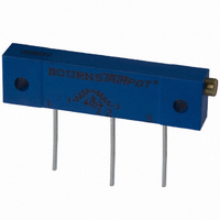
... RED WIPER 3 1 YELLOW GREEN CCW CW CLOCKWISE Listed on the QPL for style RJ12 per I MIL-PRF-22097 RoHS compliant version available † I 3059Y 7.62 6.60 (.300) (.260) 17.78 2.54 (.700) (.100) .71 ± .03 DIA. TYP. (.028 ± .001) 12.70 ± .79 (.500 ± .031) DIMENSIONS: MM/(INCHES) TOLERANCES: ± ...
Page 31
... REV 09/ design meets EIA/EIAJ/IPC/VECI I SMD standard trimmer footprint Patent #5047746 advanced I drive/wiper mechanism RoHS compliant - see page 155 for I † processing information on lead free surface mount trimmers 3214G Side Adjust 1.52 1 DIA. (.060) 1.17 2 (.046) 4.8 (.189) 2.41 2. ...
Page 32
Packaging Specifications J & G Styles .04 MAX. (.002) 4.5 MAX. (.177) 5.52 ± .05 (.217 ± .002) 5.56 ± .10 (J) 1.5 + .10/ –.00 (.219 ± .004) DIA. (.059 + .004/ –.000) 6.25 ± .10 (G) ...
Page 33
... Special resistances available. Flush adjustment screw I Meets EIA/EIAJ/IPC/VECI SMD I standard trimmer footprint Top adjust I RoHS compliant - see page 155 for I † processing information on lead free surface mount trimmers 3.9 3223W (0.153) 2.76 (0.109) DEEP 3.9 (0.153) 3.52 (0.139) 4.16 (0.164) 0.63 ...
Page 34
... EIA/EIAJ/IPC/VECI I SMD standard trimmer footprint Low CRV - DESC selected material drawing I #92021 RoHS compliant - see page 155 for † I processing information on lead free surface mount trimmers 3224G Side Adjust 1.52 1 DIA. (.060) 1.2 2 (.047) 4.8 (.189) 2.4 2. ...
Page 35
Additional Features Top and side adjust styles I J-hook, and gull-wing I Patent #5047746 advanced drive/wiper mechanism I 3224 – Packaging Specifications J & G Styles .04 MAX. (.002) 4.5 MAX. (.177) 5.52 ± .05 (.217 ± .002) 5.56 ± ...
Page 36
Electrical Characteristics Standard Resistance Range .......10 to 50K ohms (see standard resistance table) Resistance Tolerance............................±5 % std. (tighter tolerance available) Absolute Minimum Resistance .....0 ohm max. (whichever is greater) Noise....................................100 ohms ENR max. Resolution...........................See Resistance Table Insulation ...
Page 37
Electrical Characteristics Standard Resistance Range..... megohms (see standard resistance table) Resistance Tolerance..........................±10 % std. ................................(tighter tolerance available) Absolute Minimum Resistance ............ ohms max. (whichever is greater) Contact Resistance Variation ............ ohms max. ...
Page 38
Electrical Characteristics Standard Resistance Range ........................................10 to 25K ohms (see standard resistance table) Resistance Tolerance ..................±5 % std. (tighter tolerance available) Absolute Minimum Resistance ...............................0 ohm max. (whichever is greater) Noise..........................100 ohms ENR max. Resolution...................See resistance table ...
Page 39
Electrical Characteristics Standard Resistance Range ....................................... megohm (see standard resistance table) Resistance Tolerance ................±10 % std. (tighter tolerance available) Absolute Minimum Resistance ................................ ohms max. (whichever is greater) Contact Resistance Variation .............................3 ...
Page 40
Electrical Characteristics Standard Resistance Range ....................................... megohm (see standard resistance table) Resistance Tolerance ................±10 % std. Absolute Minimum Resistance ................................ ohms max. (whichever is greater) Contact Resistance Variation .............................3 ohms max. (whichever ...
Page 41
Ordering Information and Packaging Specifications Standard Resistance Table Resistance (Ohms) Resistance Code 10 100 20 200 50 500 100 101 200 201 500 501 1,000 102 2,000 202 5,000 502 10,000 103 20,000 203 25,000 253 50,000 503 ...
Page 42
... Compatible with surface mount I manufacturing processes RoHS compliant - see page 155 for † I processing information on lead free surface mount trimmers RECOMMENDED PCB RECOMMENDED PCB RECOMMENDED PCB RECOMMENDED PCB LAYOUT – “P” LAYOUT – “W” & “X” LAYOUT - "P" ...
Page 43
Packaging Specifications P Style EMBOSSED CARRIER TAPE COVER TAPE 7.50 ± .10 (.295 ± .004) 1.5 + .10/ –.00 DIA. (.059 + .004/ –.000) 4.00 ± .01 (.157 ± .004) 2.00 ± .05 (.079 ± .002) 12.00 ± ...
Page 44
Electrical Characteristics Standard Resistance Range ........................................10 to 50K ohms (see standard resistance table) Resistance Tolerance ..................±5 % std. (tighter tolerance available) Absolute Minimum Resistance ...............................0 ohm max. (whichever is greater) Noise..........................100 ohms ENR max. Resolution ................(see standard ...
Page 45
Electrical Characteristics Standard Resistance Range ....................................... megohm (see standard resistance table) Resistance Tolerance ................±10 % std. (tighter tolerance available) Absolute Minimum Resistance ohms max. (whichever is greater) Contact Resistance Variation 3292 .....................1 ...
Page 46
Electrical Characteristics Standard Resistance Range ...........................10 ohms to 2 megohms (see standard resistance table) Resistance Tolerance ................±10 % std. (tighter tolerance available) Absolute Minimum Resistance ................................ ohms max. (whichever is greater) Contact Resistance Variation .............................1 ...
Page 47
Packaging Specifications SIDE ADJUST SIDE ADJUST 3296X-1 3296X-1 28.07 ± .76 12.70 REF. (1.105 ± .030) (.500) 18 ± .76 3.81 ± .71 (.709 ± .030) (.15 ± .028) 8.89 + . (.350 ...
Page 48
Electrical Characteristics Standard Resistance Range ..........................500 ohms to 100K ohms (see standard resistance table) Resistance Tolerance ................±10 % std. Absolute Minimum Resistance ................................2 ohms max. (whichever is greater) Contact Resistance Variation ...0.5 % max. Contact Resistance (D.C. ...
Page 49
Electrical Characteristics Standard Resistance Range (Pin 1 to Pin 3) ...100 ohms to 1 megohm (see standard resistance table) Resistance Tolerance ................±20 % std. Absolute Minimum Resistance .............................................2 ohms max. Voltage Output Variation ...............+0.25 % Adjustability (VR) .........................±0.025 % Insulation ...
Page 50
Electrical Characteristics Standard Resistance Range ..................................... megohms (see standard resistance table) Resistance Tolerance ................±10 % std. (tighter tolerance available) Absolute Minimum Resistance ................................ ohms max. (whichever is greater) Contact Resistance Variation .............................1 ...
Page 51
... REV 09/ size meets EIA/EIAJ standard I trimmer footprint RoHS compliant – See page 155 for † I processing information on lead free surface mount trimmers Packaging Specifications 2.26 ± 0.20 MAX. (.089 ± .008) 0.60 MAX. (.024) 3.50 ± 0.10 (.138 ± .004) 4.00 ± ...
Page 52
... Rear adjust version available size meets EIA/EIAJ standard I trimmer footprint RoHS compliant – See page 155 for I † processing information on lead free surface mount trimmers 3303C,D-1 3-Terminal Both Sides Adjust (OPTIONAL) 3.00 (.118) 2.50 ± 0.15 3.75 (.148) (.098 ± .006) 1 ...
Page 53
Ordering Information and Packaging Specifications Packaging Specifications 2.00 ± 0.20 MAX. (.079 ± .008) 0.60 MAX. (.024) 3.50 ± 0.10 (.138 ± .004) 4.00 ± 0.010 (.157 ± .004) 4.00 ± 0.10 (.157 ± .004) 2.00 ± 0.05 ...
Page 54
Electrical Characteristics Standard Resistance Range ...........................100 ohms to 1 megohm (see standard resistance table) Resistance Tolerance ................±25 % std. (tighter tolerance available) Absolute Minimum Resistance ......................2 % max. (# ohms) Contact Resistance Variation ......3 % max. Resolution.......................Essentially infinite ...
Page 55
Electrical Characteristics Standard Resistance Range .........................100 ohms to 2 megohms (see standard resistance table) Resistance Tolerance ................±25 % std. (tighter tolerance available) Absolute Minimum Resistance ......................2 % max. (# ohms) Contact Resistance Variation ......3 % max. Resolution.......................Essentially infinite ...
Page 56
Ordering Information and Packaging Specifications Packaging Specifications Side Adjust Common Dimensions ADJ. 3309W CROSS SLOT .80 ± .15 WIDE (.031 ± .006) 3.4 ± .15 X LONG (.134 ± .006) 9.0 ± .51 2.0 ± .15 (.354 ± ...
Page 57
... REV 09/04 100 cycle rotational and seal life I RoHS compliant – See page 155 for † I processing information on lead free surface mount trimmers 3313S Position Rotor As Shown Within ±11° Of Centerline Of Terminal 2 3.61 ± .20 (.142 ± .008) 3.02 ADJ. SLOT (.119) .52 ± ...
Page 58
Additional Features Patent #5043695 assembly for seal integrity I Plastic housing for RF applications I 3313 – Ordering Information and Packaging Specifications Packaging Specifications J Style 4.0 ± 0.10 2.50 ± .10 (.157 ± .004) (.098 ± .004) .30 ± ...
Page 59
... J-hook, gull-wing and pinned I configurations Side adjust available I RoHS compliant – See page 155 for I † processing information on lead free surface mount trimmers 2 3314J-1, G-1, R-1, H-1 (Bourns Marking, Straight Slot 3314J-2, G-2, R-2, H-2 (Bourns Marking, Cross Slot) 3 ...
Page 60
Additional Features Meets EIA/EIAJ/IPC/VECI SMD I standard trimmer designs Model 3314 has been approved for I use by DESC on drawings 88039 (3314J) and 90027 (3314G) 3314 – How to Order Standard Resistance Table Resistance (Ohms) Resistance Code 10 100 ...
Page 61
Product Dimensions and Packaging Specifications Product Dimensions 3314R-1 2.55 5.00 (.100) (.197) 6.20 2 0.51 ± 0.13 (.244) (.020 ± .005) TYP. 4.50 0.51 ± 0.13 (.020 ± .005) (.177) TYP. R 0.13 ADJ. SLOT (.005) 2.45 LONG ...
Page 62
Product Dimensions and Packaging Specifications Product Dimensions 3314S-1 (Bourns Marking, Straight Slot) ADJ. SLOT 2.41 (.095) LONG 0.51 X (0.02) WIDE 0.60 X (0.236) DEEP ROTOR POSITIONED AS SHOWN WITHIN ± 22° OF CENTERLINE OF ...
Page 63
Product Dimensions and Packaging Specifications Product Dimensions 3314Z-1-(RC) E (Cross Slot) CROSS ADJUSTMENT SLOT 2.41 LONG (.095) 0.51 X WIDE (0.02) 0.51 X DEEP (0.02 ROTOR POSITIONED AS SHOWN WITHIN ± 22° OF CENTERLINE OF ...
Page 64
Electrical Characteristics Standard Resistance Range ...........................................100 " M" (see standard resistance table) Resistance Tolerance.........................±20 % Contact Resistance Variation .................................................10 % max. Resolution ..........................................Infinite Adjustment Angle .......................210 °± 15 ˚ Environmental Characteristics Power Rating ..................................0.1 watt Temperature Range ...........-10 ...
Page 65
Product Dimensions and Ordering Information Product Dimensions Model 3318B 0.8 (.032) 6.5 3.5 (.256) (.138) 3.1 (.122) 104 DIA. 4.5 (.178) Mounting 3.5 Surface (.138 2.9 0.9 2 (.114) (.035) 0.5 + 0.1/-0 0.75 + 0.1/-0 ...
Page 66
Packaging Specifications Ammo Pack Model 3318S 6.3 6.5 1.5 (.248) (.256) (.059) 3.5 0.8 (.138) (.031) MOUNTING 4.5 SURFACE (.177) 2 4.8 2.5 ± .04 0.9 (.189) (.098 ± .002) (.035) 2.0 0.75 +0.1/-0 (.079) (.030 +.004/-0) 1 ...
Page 67
Packaging Specifications Ammo Pack Model 3318B 0.8 (.032) 6.3 3.5 (.248) 1.5 3.5 (.138) (.060) (.138) 2.0 4.8 (.079) (.189) 4.5 (.177) 3.5 (.138) 1 2.5 ± 0.5 2.3 (.098 ± .020) (.091) 0.9 (.035) 2.8 0.3 (.110) ...
Page 68
Electrical Characteristics Standard Resistance Range .....................................100 to 1 megohm (see standard resistance table) Resistance Tolerance .......................±30 % Contact Resistance Variation ....10 % max. Resolution.........................................Infinite Adjustment Angle .....................210 ° ±20 ° Environmental Characteristics Power Rating 100-500K ohms ................................50 V >500K ohms......................................25 ...
Page 69
Packaging Specifications Ammo Pack Model 3318K 6.8 (.268) 2.05 (.081) 2.5 ± .35 4.5 (.098 ± .014) (.833) 8.0 (.315) DIMENSIONS: MM/(INCHES) TOLERANCES: ±.25/(±.010) EXCEPT WHERE NOTED Ammo Pack Model 3318F 6.4 (.252) 3.2 3.2 2 (.126) (.126) ...
Page 70
Electrical Characteristics Standard Resistance Range .....................................100 to 1 megohm (see standard resistance table) Resistance Tolerance ................±25 % std. End Resistance ......................2 % max. (# ohms) Contact Resistance Variation ..................................................3 % max. Resolution.........................................Infinite Adjustment Angle ......................235 ° nom. Environmental ...
Page 71
Product Dimensions and Ordering Information Side Adjust Side Adjust ADJ. 3319W-1 3319W-1 CROSS SLOT .80 ± .15 WIDE (.031 ± .006) 2.0 ± .15 X DEEP (.079 ± .006) 9.0 ± .51 3.4 ± .15 X LONG (.354 ...
Page 72
Electrical Characteristics Standard Resistance Range ....................................... megohm (see standard resistance table) Resistance Tolerance ................±10 % std. (closer tolerance available) Absolute Minimum Resistance ......................................... ohms (whichever is greater) Contact Resistance Variation .............................3 ohms ...
Page 73
Packaging Specifications and Ordering Information Packaging Specifications SIDE ADJUST SIDE ADJUST 3329M-1 3329M-1 12.70 REF. (.500) 26.4 ± .76 9.4 ± .5 (1.039 ± .030) (.370 ± .020 4.0 ± 0 1.0/ - ...
Page 74
Electrical Characteristics Standard Resistance Range ....................................... megohm (see standard resistance table) Resistance Tolerance ................±10 % std. (tighter tolerance available) Absolute Minimum Resistance ................................ ohms max. (whichever is greater) Contact Resistance Variation ................................ ...
Page 75
... CLOCKWISE Constructed with lead free materials I Rotor stop for “in circuit” adjustment I RoHS compliant – See page 155 for † I processing information on lead free surface mount trimmers Standard Resistance Table Resistance (Ohms) Resistance Code 100 101 200 201 500 501 ...
Page 76
Additional Features Automated placement compatible I 3342 – Packaging Specifications 2.29 REF. 0.20 (.090) (.008) R MAX. 0.3 ± 0.05 3 ° ± 1 ° (0.12 ± .002) 3.10 ± 0.1 (.122 ± .004) 8.0 + 0.3/-0.1 (.315 +.118/-.004) 3.5 ...
Page 77
Electrical Characteristics Standard Resistance Range ........................................10 to 50K ohms (see standard resistance table) Resistance Tolerance ..................±5 % std. (tighter tolerance available) Absolute Minimum Resistance ..........................1 0.5 ohms max. (whichever is greater) Noise..........................100 ohms ENR max. Resolution ..................See standard ...
Page 78
Electrical Characteristics Standard Resistance Range ..................................... megohms (see standard resistance table) Resistance Tolerance ................±20 % std. (tighter tolerance available) Absolute Minimum Resistance .............................................2 ohms max. Contact Resistance Variation ...............................1 ohm max. (whichever is greater) Adjustability ...
Page 79
Electrical Characteristics Standard Resistance Range Linear...................1K ohms to 1 megohm Total Resistance Tolerance Linear Tapers .................................±20 % Independent Linearity.........................±5 % Absolute Minimum Resistance .....................................2 ohms maximum Effective Electrical Angle ......240 ° nominal Contact Resistance Variation ...........................................1 ohm ...
Page 80
Product Dimensions COMMON DIMENSIONS 3360C MOUNTING DIA. 3.35 5.59 ± .25 (.131) (.220 ± .010) ACROSS FLATS 3.20 ± .25 (.126 ± .010) .38 (.015) MIN. STANDOFF 2.54 ± .25 2.54 ± .25 (.100 ± .010) (.100 ± ...
Page 81
... Compatible with surface mount I manufacturing processes RoHS compliant version available – † I See page 155 for processing information on lead free surface mount trimmers 3361S 6.71 ± 0.12 (.264 ± .005) Electrical adjustment 2.77 ± 0.13 LONG 7.37 ± 0.38 (.109 ± .005) (.290 ± ...
Page 82
Packaging Specifications and Ordering Information Packaging Specifications P Style EMBOSSED CARRIER TAPE 5.84 ±0.1 COVER TAPE (.230 ±.004) 7.50 ±.10 (.295 ±.004) 1.5 +.10/ –.00 DIA. (.059 +.004/ –.000) 4.00 ±.01 (.157 ±.004) 2.00 ±.05 (.079 ±.002) 12.00 ...
Page 83
Electrical Characteristics Standard Resistance Range ..................................... megohms (see standard resistance table) Resistance Tolerance ................±10 % std. (tighter tolerance available) Absolute Minimum Resistance ...... ohms (whichever is greater) Contact Resistance ...
Page 84
Product Dimensions, Packaging Specifications and Ordering Information Product Dimensions The Model 3362P is available with a knob for finger adjustment. Add suffix letter “T” to order code. 6.71 (.264) ADJ. CROSS SLOT 7.04 0.36 (.277) LONG (.014) 1 ...
Page 85
... TOLERANCES: ±.25/(±.010) EXCEPT WHERE NOTED Recommended for reflow solder I processing only RoHS compliant – See page 155 for † I processing information on lead free surface mount trimmers 3364A, B 3364A, B 3-Terminal 3-Terminal 3.80 (.150) 2.50 ± 0.15 (.098 ± .006) 0.55 ± 0.15 (.022 ± ...
Page 86
Packaging Specifications and Ordering Information Packaging Specifications 2.20 ± 0.20 (.087 ± .008) 0.60 (.024) 5.51 ± 0.05 (.217 ± .002 4.00 ± 0.10 ORIENTATION (.157 ± .004) 8.00 ± 0.10 (.315 ± .004) 2.00 ± ...
Page 87
Electrical Characteristics Standard Resistance Range ..................................... megohms (see standard resistance table) Resistance Tolerance ................±10 % std. (tighter tolerance available) Absolute Minimum Resistance .............................................2 ohms max. Contact Resistance Variation ................................ ohms max. (whichever is greater) Adjustability ...
Page 88
Product Dimensions Common Dimensions Top Adjust ADJ. SLOT .76 WIDE (.030) 9.53 5.97 ±.89 .76 X DEEP (.375) (.235 ±.035) (.030) 3.15 4.83 X LONG (.124) (.190) 9.53 (.375) .51 ±.05 (.020 ±.002) .38 5.64 MIN. (.015) (.222) ...
Page 89
Packaging Specifications and Ordering Information Packaging Specifications SIDE ADJUST 3386W-1 27.56 ± .76 12.70 REF. (1.085 ± .030) (.500) 18 ± .76 (.709 ± .030) 3.81 ± . (.15 ± .028) 3 8.89 + .76 /- ...
Page 90
Electrical Characteristics Standard Resistance Range .................................2.5 and 5 megohms Resistance Tolerance .......................±20 % Contact Resistance Variation ......2 % max. Adjustability Voltage Divider............................±0.05 % Rheostat .....................................±0.15 % Resolution.........................................Infinite Insulation Resistance @ 1 KV D.C. ................................1,000 megohms min. Dielectric Strength (5,000 foot ...
Page 91
Electrical Characteristics Standard Resistance Range ...........................100 ohms to 1 megohm (see standard resistance table) Resistance Tolerance ................±20 % std. Absolute Minimum Resistance .............................................2 ohms max. Voltage Output Variation ...............±0.25 % Adjustability (VR) .........................±0.025 % Insulation Resistance @ 500 vdc 1,000 ...
Page 92
... DIMENSIONS: MM/(INCHES) 2 WIPER CCW CLOCKWISE RoHS compliant † – See page 155 for I processing information on lead free surface mount trimmers Standard Resistance Table Resistance Resistance Part (Ohms) Code Marking 100 101 12 200 201 22 500 501 52 1,000 ...
Page 93
... WIPER 3 1 CCW CW CLOCKWISE 2 mm size meets EIA/EIAJ standard I trimmer footprint RoHS compliant – See page 155 for † I processing information on lead free surface mount trimmers Packaging Specifications 5.5 0.3 (.217) (.008) 0.06 (.002) 1.5 (.059) 8.0 (.315) 2.75 (.108) 3.5 ± 0.05 1.75 ± ...
Page 94
... Cross Slot Rotor Resistance Code Embossed Tape Designator E = 2500 pcs./7 ˝ Reel (Standard 9000 pcs./13 ˝ Reel RoHS compliant – See page 155 for I † processing information on lead free surface mount trimmers Packaging Specifications 0.2 5.5 (.008) (.217) 0.06 (.002) 2.4 (.094) 8 ...
Page 95
... DIMENSIONS: MM/(INCHES) RoHS compliant † – See page 155 for I processing information on lead free surface mount trimmers Standard Resistance Table Resistance Part Part (Ohms) Marking Marking 500 52 501 1,000 13 102 2,000 23 ...
Page 96
Electrical Characteristics Standard Resistance Range ...........................100 ohms to 1 megohm (see standard resistance table) Resistance Tolerance ................±20 % std. (tighter tolerance available) Absolute Minimum Resistance # 500 Ohms.......................10 ohms max. > 500 Ohms ....................2 % max Contact Resistance ...
Page 97
TC86 – Suggested PCB Layout and Ordering Information Suggested PCB Layout – Style F 1.0 5.0 ± 0.1 (.040) (.197 ± .004) DIA. 3 PLCS. 5.0 ± 0.1 (.197 ± .004) Suggested PCB Layout – Styles 2.5 ...
Page 98
Electrical Characteristics Standard Resistance Range ...........................100 ohms to 1 megohm (see standard resistance table) Resistance Tolerance ................±20 % std. Absolute Minimum Resistance #500 Ohms ........................10 ohms max. >500 Ohms .....................2 % max Contact Resistance Variation ......5 % max. ...
Page 99
...
Page 100
Mil-Spec Numbering System – Defined Non-Wirewound RJ Styles MIL-PRF-22097 Style Characteristic Temperature Coefficient Max. ±100 ppm/°c Contact Resistance Variation Max Thermal Shock 1 % Humidity 1 % Shock 1 % Vibration 1 % Load Life 2 % Low ...
Page 101
Mil-Spec Numbering System – How to Order Bourns High Reliability Mil-Spec Part Numbers Order By M39015/2-003(TS)(FR) RTR22D(TS)501(FR) M39015/2-004(TS)(FR) RTR22D(TS)102(FR) M39015/2-005(TS)(FR) RTR22D(TS)202(FR) M39015/2-006(TS)(FR) RTR22D(TS)502(FR) M39015/2-007(TS)(FR) RTR22D(TS)103(FR) M39015/2-008(TS)(FR) RTR22D(TS)203(FR) M39015/3-006(TS)(FR) RTR24D(TS)501(FR) M39015/3-007(TS)(FR) RTR24D(TS)102(FR) M39015/3-008(TS)(FR) RTR24D(TS)202(FR) M39015/3-009(TS)(FR) RTR24D(TS)502(FR) M39015/3-010(TS)(FR) RTR24D(TS)103(FR) *May also order ...
Page 102
Qualified Part Numbers RT/RTR24 (Commercial Model 3290) Standard RT24C2_____ Values P W (ohms) 10 RT24C2P100 RT24C2W100 20 RT24C2P200 RT24C2W200 50 RT24C2P500 RT24C2W500 100 RT24C2P101 RT24C2W101 200 RT24C2P201 RT24C2W201 500 RT24C2P501 RT24C2W501 1K RT24C2P102 RT24C2W102 2K RT24C2P202 RT24C2W202 5K RT24C2P502 RT24C2W502 ...
Page 103
Qualified Part Numbers RJ24 (Commercial Model 3296 for Model 3292 for L) Standard RJ24F_____ Values L P (ohms) 10 RJ24FL100 RJ24FP100 20 RJ24FL200 RJ24FP200 50 RJ24FL500 RJ24FP500 100 RJ24FL101 RJ24FP101 200 RJ24FL201 RJ24FP201 500 RJ24FL501 RJ24FP501 1K ...
Page 104
Qualified Part Numbers RJ12 (Commercial Model 3059) Standard RJ12F_____ Values P (ohms) 10 RJ12FP100 20 RJ12FP200 50 RJ12FP500 100 RJ12FP101 200 RJ12FP201 500 RJ12FP501 1K RJ12FP102 2K RJ12FP202 5K RJ12FP502 10K RJ12FP103 20K RJ12FP203 25K RJ12FP253 50K RJ12FP503 100K RJ12FP104 ...
Page 105
Electrical Characteristics Standard Resistance Range ........................................10 to 20K ohms (see standard resistance table) Resistance Tolerance ..................±5 % std. (tighter tolerance available) Absolute Minimum Resistance ...............................0 ohm max. (whichever is greater) Noise..........................100 ohms ENR max. Resolution.................See Resistance Table ...
Page 106
Electrical Characteristics Standard Resistance Range RT22 ...............................50 to 20K ohms RTR22 ...........................500 to 20K ohms (see standard resistance table) Resistance Tolerance ..................±5 % std. (tighter tolerance available) Absolute Minimum Resistance ...............................0 ohm max. (whichever is greater) Noise..........................100 ...
Page 107
Electrical Characteristics Standard Resistance Range RT24 ...............................10 to 10K ohms RTR24 ...........................500 to 10K ohms (see standard resistance table) Resistance Tolerance ..................±5 % std. (tighter tolerance available) Absolute Minimum Resistance ...............................0 ohm max. (whichever is greater) Noise..........................100 ...
Page 108
Electrical Characteristics Standard Resistance Range .......................................... ohms (see standard resistance table) Resistance Tolerance ..................±5 % std. (tighter tolerance available) Absolute Minimum Resistance .............................0. ohm max. (whichever is greater) Noise..........................100 ohms ENR max. Resolution...................See resistance table ...
Page 109
Electrical Characteristics Standard Resistance Range ....................................... megohm (see standard resistance table) Resistance Tolerance ................±10 % std. (tighter tolerance available) Absolute Minimum Resistance ................................ ohms max. (whichever is greater) Contact Resistance Variation ...............................1 ...
Page 110
Electrical Characteristics Standard Resistance Range .............................10 ohms to 1 megohm (see standard resistance table) Resistance Tolerance ................±10 % std. (tighter tolerance available) Absolute Minimum Resistance ..............................................1 ohm max. Contact Resistance Variation ................................ ohms max. (whichever is greater) ...
Page 111
Electrical Characteristics Standard Resistance Range ....................................... megohm (see standard resistance table) Resistance Tolerance ................±10 % std. Absolute Minimum Resistance ..............................................1 ohm max. Contact Resistance Variation .............................3 ohms max. (whichever is greater) Adjustability Voltage........................................±0.01 % Resistance ...
Page 112
Electrical Characteristics Standard Resistance Range ....................................... megohm (see standard resistance table) Resistance Tolerance ................±10 % std. (tighter tolerance available) Absolute Minimum Resistance ........ ohms max. (whichever is greater) Contact Resistance Variation........3 ohms ...
Page 113
Electrical Characteristics Standard Resistance Range ....................................... megohm (see standard resistance table) Resistance Tolerance ................±10 % std. (closer tolerance available) Absolute Minimum Resistance ......................................... ohms (whichever is greater) Contact Resistance Variation .............................3 ohms ...
Page 114
...
Page 115
...
Page 116
Specifications* Standard Electrical Travel ....................................0.15, 0.25, 0.35 in. (3.81, 6.35, 8.89 mm) Standard Resistances ..........................1K to 50K ohms (±20 %) Independent Linearity.........................±5 % Resolution.........................................Infinite Power Rating @ 70 °C (158 °F) .................................................0.125 watt Operating Temperature Range ....................................-55 °C to +125 ...
Page 117
Specifications* Standard Electrical Travel ..................................0.2, 0.3, 0.4, 0.5 in. (5.08, 7.62, 10.16, 12.70 mm) Standard Resistances ................1K ohms to 50K ohms (±20 %) Independent Linearity.........................±5 % Resolution.........................................Infinite Power Rating @ 70 °C (158 °F) Range 2, 3 .................................0.12 watt Range ...
Page 118
...
Page 119
...
Page 120
Materials & Finishes Insulator ....Glass reinforced thermoplastic, UL 94V-0 rated, black Contact ...................................Copper alloy Finish Underplating ...............30 µ˝ µ˝ nickel Contact Area.............30 µ˝ Au over nickel Operating Characteristics Electrical Current Rating .......................3 A/contact Voltage Rating ...................................60 V Contact ...
Page 121
Materials & Finishes Insulator ....Glass reinforced thermoplastic, UL 94V-0 rated, black Contact ...................................Copper alloy Finish Underplating ...............30 µ˝ µ˝ nickel Contact Area.............30 µ˝ Au over nickel Operating Characteristics Electrical Current Rating .......................3 A/contact Voltage Rating ...................................60 V Contact ...
Page 122
Packaging Specifications TAPE 0.3 (.012) 5.15 (.203 1.5 DIA. (.059) 9.74 2.00 (.383) (.079) 4.00 (.157) 12.00 (.472) 1.75 (.069) A REEL 1.5 EQUAL SPACED 3 PLCS. (.059) 20.2 DIA. 13.0 (.795) 3.00 (.512) (.118) DIA. ...
Page 123
Materials & Finishes Insulator ....Glass reinforced thermoplastic, UL 94V-0 rated, black Contact ...................................Copper alloy Finish Underplating ...............30 µ˝ µ˝ nickel Contact Area.............30 µ˝ Au over nickel Termination..................................Tin alloy (meets MIL-STD-202, method 208) Operating Characteristics Electrical Current Rating .................DC ...
Page 124
Materials & Finishes Insulator .....Glass reinforced thermoplastic UL 94V-0 rated, black Contact ...................................Copper alloy Finish Underplating ...............30 µ˝ µ˝ nickel Contact Area ..................30 µ˝ Au over Ni Termination..................................Tin alloy (meets MIL-STD-202, method 208) Operating Characteristics Electrical Current Rating ...
Page 125
...
Page 126
Electrical Characteristics Contact Rating Maximum Current ...............100 mA max. Maximum Voltage .............................16 V Contact Timing.......................Non-shorting Contact Resistance................2 ohms max. Insulation Resistance ...................................100 megohms min. Dielectric Strength ........................250 VAC General Characteristics Switch Type........................................SPDT Operating Temperature Range ....................................-55 °C to +125 °C ...
Page 127
Packaging Specifications and Reflow Soldering Profile Packaging Specifications 7813J 4.0 ± 0.1 2.5 ± 0.1 (.157 ± .004) (.098 ± .004) .30 ± 0.1 (.012 ± .004) 5.52 ± 0.18 (.217 ± .007) 4.0 ± 0.1 (.157 ± ...
Page 128
Electrical Characteristics Contact Rating Maximum Current ...............100 mA max. Maximum Voltage .............................16 V Contact Timing.......................Non-shorting Contact Resistance................2 ohms max. Insulation Resistance ...100 megohms min. Dielectric Strength ........................250 VAC General Characteristics Switch Type........................................SPDT Operating Temperature Range ....................................-55 °C to +125 °C ...
Page 129
Packaging Specifications and Reflow Soldering Profile Packaging Specifications J Style .36 MAX. (.014) 2.74 ±.10 (.101 ±.004) 5.52 ±0.5 (.217 ±.020) 1.5 + .10/ –.00 DIA. (.059 + .004.–.00) 5.26 ±.10 (.207 ±.004) 4.00 ±.10 (.157 ±.004) 5.26 ...
Page 130
Electrical Characteristics Contact Rating Maximum Current ...............100 mA max. Maximum Voltage .............................16 V Contact Timing.......................Non-shorting Contact Resistance................2 ohms max. General Characteristics Switch Type........................................SPDT Operating Temperature Range ....................................-55 °C to +125 °C Storage Temperature Range ....................................-55 °C to +125 °C Thermal ...
Page 131
Electrical Characteristics Contact Rating Maximum Current ...............100 mA max. Maximum Voltage .............................16 V Contact Resistance .....100 milliohms max. Insulation Resistance ...100 megohms min. Dielectric Strength ........................250 VAC General Characteristics Switch Type .........................Normally open Operating Temp. Range ..-55 °C to +125 ...
Page 132
Packaging Specifications J Style Reel .30 MAX. (.012) 4.3 ±.10 (.169 ±.004) 5.50 ±0.05 (.217 ±.002) 1.5 +.10/ –.00 DIA. (.059 +.004/ –.00) 5.26 ±.10 (.207 ±.004) 4.00 ±.10 (.157 ±.004) 5.26 ±.10 2.00 ±.05 (.207 ±.004) (.079 ...
Page 133
Electrical Characteristics Electrical Life ..........1,000 operation cycles per switch min. Non-Switching Rating ......100 mA, 50 VDC Switching Rating ................25 mA, 24 VDC Contact Resistance.........100 mohms max. Insulation Resistance .....100 Mohms min., DC 100 V min. Dielectric Strength...AC 300 V for ...
Page 134
SDHH Series – Packaging Specifications 7.00 ± 0.13 2.24 ± 0.10 (0.088 ± .004) (0.276 ± 0.005) 5˚ MAX 12.00 ± 0.13 (0.472 ± 0.005) 5.00 ± 0.13 (0.197 ± 0.005) 1.75 ± 0.10 (.069 ± .004) 2.00 ± 0.05 ...
Page 135
Electrical Characteristics Electrical Life............2,000 operations min. per switch, 24 VDC Non-Switching Rating ......100 mA, 50 VDC Switching Rating ................25 mA, 24 VDC Contact Resistance (@ current 100 mA) .......................50 milliohms max. at initial 100 milliohms max. after life ...
Page 136
Electrical Characteristics Electrical Life ..................500,000 cycles min. for 260 g 1,000,000 cycles min. for 100 g, 160g Rating................................. Contact Resistance .....100 milliohms max. Insulation Resistance .................100 megohms, DC 500 V min. Dielectric Strength...250 V AC for ...
Page 137
SDT Series – Product Dimensions SDTA-610/620/630/650/660 6.20 (.244) 4.30 (.169 7. (.283) 4.00 1.80 (.157) (.071) 0.40 (.016 0.70 3.50 ± 0.50 (.028) 4.50 ± 0.20 (.138 ± ...
Page 138
SDT Series – Product Dimensions, Packaging Specifications and Ordering Information Product Dimensions SDTX-244 12.0 (.472) 8.0 (.315 5.0 ± 0. (.197 ± .008 1.70 7.10 DIA. 4.30 (.067) ...
Page 139
Electrical Characteristics Electrical Life ....................50,000 cycles min. for 260 g 500,000 cycles min. for 100 g, 160 g Rating ................................ Contact Resistance.........100 mohms max. Insulation Resistance ......100 Mohms min., DC 500 V min. Dielectric Strength...AC 250 ...
Page 140
SDTM Series – Packaging Specifications Packaging Specifications SDTM-610/620/630/644/648/650(TR) 16.00 +0.30/-0.10 2.0 ± 0.10 (.630 + .012/-.004) (.079 ± .004) 1.50 +0.25/-0.00 (.059 +.010/-0.00) DIA. 4.00 ± 0.10 (.157 ± .004) 12.00 ± 0.10 (.472 ± .004) 1.50 + 0.10/-0.00 (.059 ...
Page 141
Electrical Characteristics Electrical Life............2,000 operations min. per switch, 24 VDC Non-Switching Rating ......100 mA, 50 VDC Switching Rating ................25 mA, 24 VDC Contact Resistance (@ current 100 mA) .......................50 milliohms max. at initial 100 milliohms max. after life ...
Page 142
SND Series – Packaging Specifications Product Dimensions 12.0 ± 0.1 (.472 ± .004) 11.0 ± 0.1 (.433 ± .004) 8.0 +0.2/-0.1 (.315 +.008/-.004) 11.0 ± 0.1 (.433 ± .004) 2.5 (.100) 5.0 ± 0.1 (.20 ± .004) 0.5 (.019) Reflow ...
Page 143
Electrical Characteristics Electrical Life...............100,000 cycles min. Rating ................................ Contact Resistance.........100 mohms max. Insulation Resistance .......100 Mohms min. DC 500 V min. Dielectric Strength...AC 250 V for 1 minute Contact Arrangement.......1 pole 1 position Environmental Characteristics Mechanical ...
Page 144
ST(H,M,J)W Series – Packaging Specifications and Ordering Information Packaging Specifications STMW-660/667//680/690(TR) STJW-660/667/680/690(TR) 16.00 +0.30/-0.10 2.0 ± 0.10 (.630 + .012/-.003) (.079 ± .003) 1.50 +0.25/-0.00 (.059 +.010/-0.00) DIA. 4.00 ± 0.10 (.157 ± .003) 8.00 ± 0.10 (.314 ± .003) ...
Page 145
Electrical Characteristics Max. Power Rating....12 VDC max Contact Resistance .....100 milliohms max. Insulation Resistance ....................50 megohms min., 100 VDC Dielectric Strength...AC 100 V for 1 minute Bounce On ............................................3 ms max. Off ..........................................10 ms max. Circuit ........................................N.O. SPST ...
Page 146
Electrical Characteristics Max. Power Rating....12 VDC max Contact Resistance .....100 milliohms max. Insulation Resistance ..................100 megohms min., 100 VDC Dielectric Strength...AC 250 V for 1 minute Bounce On ............................................3 ms max. Off ..........................................10 ms max. Circuit ........................................N.O. SPST ...
Page 147
Electrical Characteristics Electrical Life ...............50,000 Cycles for 160 gf, 320 gf Rating ..................................50 mA, 12 VDC Contact Resistance ................100 m" max. Insulation Resistance ...........................100 M" min. @ 500 VDC Dielectric Strength...........250 VAC/1 minute Contact Arrangement ..........................SPST Environmental Characteristics Operation Temperature ...
Page 148
...
Page 149
...
Page 150
... For example, are you aware that the trimmers and other mechanical components on your boards may face a more extreme environment during boardwashing on your own production line, than they ever will in use? For those trimmers that may need to be reset, are you remembering to select and mount the trimmers to provide easy ...
Page 151
Applications/Processing Guide – Standard and Lead Free Trimming Potentiometers and Definitions The following terms and definitions have been edited from the Industrial Standard published by the Variable Electronics Components Institute intended to encourage standardization in communication and understanding ...
Page 152
... Absolute minimum resistance and end resistance are synonymous for continuous rotation trimmers. TEMPERATURE COEFFICIENT OF RESISTANCE: The unit change in resistance per degree Celsius change from a reference temperature, expressed in parts per million per ...
Page 153
Applications/Processing Guide – Standard and Lead Free Test Current (±20 %) Total Resistance Range 200 5 ma 200 < < 200K 200 ua 200K < Rt ...
Page 154
Applications/Processing Guide – Standard and Lead Free Processability “Processability” refers to the ability of the unit to withstand the production-line processes associated with the finishing steps on the PC boards. Typically, both SMT and through-hole products are subjected to similar ...
Page 155
... Bourns® trimmers exhibit excellent stability under all specified conditions. Stability is most often a concern when cermet trimmers are used in low current “dry” circuits (50 uA and below). Under these conditions the contact resistance may vary, making the wiper appear unstable. This is most noticeable in some rheostat applications ...
Page 156
... MIL-R-39035, the maximum CRV All Bourns® trimmers meet this standard ( ohms, whichever is greater). For applications that demand a more rigorous standard, some Bourns® trimmers are rated ohms, and many others ohm. 154 Power Rating — The ambient temperature at which the trimmer will operate has an important bearing on power rating. Power ratings are usually specified at 70 ° ...
Page 157
... Units that are board mounted for environmental testing must see a peak temperature in the reflow zone, as specified. This is to ensure that all test units will see “worst case conditions”. 4. Ramp down rate to be measured from 255 °C to 150 °C. 5. Process Description 8 does not apply to open frame trimmers. Temperature Room temperature ...
Page 158
Standard Soldering and Cleaning Processes This application note is designed to provide step-by-step processing recommendations. It covers the popular Surface Mount Component (SMC) soldering processes currently in use and provides recommendations and cautions for each step. Since many variations of ...
Page 159
Standard Soldering and Cleaning Processes 6 7 Solder Solder Reflow; Hot Air, Flow (Wave) IR and Vapor Phase GENERAL GENERAL Preheat sufficiently For maximum com- using both time ponent reliability and temperature and performance, to vaporize all minimize the time ...
Page 160
Standard Soldering/Cleaning Methods Process Hot Air Step Infrared (Solvent) 1. Solder Paste Printing N 2. Adhesive Application 3. Component Placement N 4. Adhesive Cure 5. Flux Application 5. Flux Application 5. Flux Application 5. Flux Application 6. Solder (Reflow) N ...
Page 161
Standard Soldering/Cleaning Methods Flow Wave Wave (Solvent) (Semi-Aqueous 260/5 260/5 215 215 Material Wave Wave (Aqueous) (No Clean Rosin Rosin Organic Acid ...
Page 162
Factory Installed Panel Mount Trimpot® Potentiometer Panel Mounting Options and Hardware Many Trimpot® Potentiometers are available for panel mount application. This product option provides for maximum design flexibility. To order Trimpot® Potentiometers with panel mount hardware attached by the factory, ...
Page 163
Factory Installed Panel Mount Models 3292 X, L and W Styles 6.10 (.240) 3.05 (.120) ADJ. SLOT .243 BUSHING LONG (.010) 10-32 UNF-2A .064 THD. WIDE (.003) OPT. BEND .064 DEEP DOWN ANTI- (.003) ROTATION TAB 6.35 (.250) 10.92 (.430) ...
Page 164
Customer Installed Panel Mount – Unsealed H-58P Panel Mount 1-1/4 Inch Rectangular Multiturn Modules HEX NUT AND LOCKWASHER 10.31 (.406) MAX. 7.95 33.35 (.313) (1.31) 6.35 (.250) BUSHING 10-32 NF-2 THD 1.52 3.30 10.0 TO (.060) (.130) (.394) ADJ. SLOT ...
Page 165
Customer Installed Panel Mount 3/8 Inch Square Multiturn Models H-114P/115P/116P Panel Mount 6.10 (.240) 3.05 (.120) ADJ. SLOT .243 BUSHING LONG (.010) 10-32 UNF-2A .064 THD. WIDE (.003) OPT. BEND .064 DEEP DOWN ANTI- (.003) ROTATION TAB 11.43 6.35 (.450) ...
Page 166
Hardware for Special Mounting Applications H-82 Panel Seal For all panel mounts with size 10-32 bushings. 4.83 (.190) STAINLESS STEEL CUP WASHER 7.37 .381 (.290) (.015) 1.02 (.040) .89 4.83 (.035) (.190) RUBBER O RING To be used with the ...
Page 167
H-90 STAINLESS STEEL BLADE RECESSED .254 (.010) H-91* STAINLESS STEEL BLADE RECESSED .254 (.010) 2.29 .457 BLADE WIDE X THICK (.090) (.018) *H-91 RECOMMENDED FOR USE WITH TRIMMER MODELS 3224 AND 3214. H-92-1* STAINLESS STEEL BLADE RECESSED .381 (.015) 1.02 ...
Page 168
... Trimming potentiometers perform a variety of circuit adjustments in all types of electronic equipment. The variety of physical configurations available and the ability to withstand today's manufacturing environment offers the designer flexibility in selecting the best trimmer for the application. Around the world, trimmers are used in virtually every electronic market. H-841 ...
Page 169
Part Numbers Each kit contains samples of each of the part numbers. Part numbers could change based on latest offering. Refer to website – additional kits may be available. Kit Number H-848 3048L-2-103 3046L-1-103 3048L-5-203 3046L-3-203 Part Numbers Each kit ...
Page 170
Part Numbers Each kit contains samples of each of the part numbers. Part numbers could change based on latest offering. Refer to website – additional kits may be available. Kit Numbers H-845 H-846 7813J-1-023 7914J-1-000 7813S-1-051 SDTA-610-K 7814G-1-023 SDTG-630-N 7814J-1-051 ...
Page 171
...
Page 172
Worldwide Sales Offices Country Phone Benelux: +31-70-3004333 Brazil: +55 11 5505 0601 China: +86-21-64821250 France: +33-254-735151 Germany: +49-69-80078212 Hong Kong: +852-2411 5599 Ireland: +44-1276-691087 Italy: +39-02-38900041 Japan: +81-49-269 3204 Singapore: +65-63461933 Switzerland: +41-41-7685555 Taiwan: +886-2-25624117 UK: +44-1276-691087 USA: +1-951-781-5500 Non-Listed ...