3059Y-1-500LF Bourns Inc., 3059Y-1-500LF Datasheet - Page 131
3059Y-1-500LF
Manufacturer Part Number
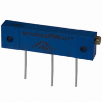
3059Y-1-500LF
Description
TRIMPOT 50 OHM 1.25"REC CER MT
Manufacturer
Bourns Inc.
Series
3059 - Sealedr
Specifications of 3059Y-1-500LF
Temperature Coefficient
±100ppm/°C
Resistance (ohms)
50
Termination Style
PC Pin
Power (watts)
1W
Tolerance
±10%
Number Of Turns
22
Adjustment Type
Side Adjustment
Resistive Material
Cermet
Mounting Type
Chassis Mount
Package / Case
Rectangular - 1.250" L x 0.190" W x 0.315" H (31.75mm x 4.83mm x 8.00mm)
Track Resistance
50ohm
No. Of Turns
22
Resistance Tolerance
± 10%
Power Rating
1W
Potentiometer Mounting
Through Hole
Resistance
50 Ohms
Operating Temperature Range
- 55 C to + 150 C
Element Type
Cermet
Dimensions
6.10 mm W x 31.75 mm L
Product
Trimmers
Taper
Linear
Rohs Compliant
Yes
Lead Free Status / RoHS Status
Lead free / RoHS Compliant
Lead Free Status / RoHS Status
Lead free / RoHS Compliant, Lead free / RoHS Compliant


Contact Rating
Contact Resistance .....100 milliohms max.
Insulation Resistance ...100 megohms min.
Dielectric Strength ........................250 VAC
Switch Type .........................Normally open
Operating Temp. Range ..-55 °C to +125 °C
Storage Temp. Range ....-55 °C to +125 °C
Seal Test ...........................85 °C Fluorinert*
Vibration ..............................................20 G
Shock ................................................100 G
Actuator Force ..........................300 ±100 g
Pushover Strength (S Style) ........2 kG min.
Cycle life, loaded..........100,000 actuations
Contact resistance.......100 milliohms max.
Cover Material......................Stainless steel
Base Material ......Thermoplastic, UL 94V-0
Terminal Material .............Phosphor bronze
Dome Material......................Stainless steel
Actuator Material.............High temperature
Marking ......................Manufacturer’s code
Packaging Options
Model
Terminal
Switch Type
Product Code for Button Height
Embossed Tape
(Option applicable to Styles J, G & S only –
Consult Factory. Omit for Tube packaging.)
FMS = From Mounting Surface
FTS = From Top Surface
Electrical Characteristics
General Characteristics
Mechanical Characteristics
Physical Characteristics
How To Order
(For Style S)
-000 = 1.68 mm FTS
-024 = Flush Actuator
H = Through-hole Z = Right Angle
J = J-Hook
Maximum Current ...............100 mA max.
Maximum Voltage .............................16 V
J & G .............500 pcs./reel; 50 pcs./tube
S ..................200 pcs./reel; 100 pcs./tube
H...........................................50 pcs./tube
(For Styles J, G, and H)
-000 = 4.0 mm FMS
-024 = 2.4 mm FMS (Flush Actuator)
-032 = 3.2 mm FMS
-050 = 5.0 mm FMS
G, J = 500 pcs./reel S = 200 pcs./reel
-1 = N.O. Au Contacts
G = Gull Wing
7914 J - 1 - 000 E
-032 = 0.91 mm FTS
-050 = 2.7 mm FTS
and date code
silicon rubber
7914 – 4 mm SMD & Through-hole
Sealed Key Switch
Features
I
I
I
I
7914J
J-Hook
*”Fluorinert” is a registered trademark of 3M Co.
†
Specifications are subject to change without notice.
Customers should verify actual device performance in
their specific applications.
(.197)
7914G
Gull Wing
6.20
RoHS Directive 2002/95/EC Jan 27 2003 including Annex.
Product Dimensions
5.00
Compatible with most surface mount
soldering processes
Compatible with popular vacuum
pick-and-place equipment
J-hook, gull-wing & pinned
configurations
Sealed for board washing
1
1
1
1
(.189)
4.80
(.189)
4.80
2 PLCS.
(.100)
2
2 PLCS.
2.54
(.100)
2
2.54
7A
7A
2
2
(.030)
0.76
TYP.
(.030)
0.76
TYP.
(.177)
(.177)
4.50
4.50
(.157)
4.00
RECOMMENDED PCB LAYOUT
RECOMMENDED PCB LAYOUT
(.094)
(.150)
2.40
(.217)
(.157)
4.00
3.8
5.5
(.094)
5 MAX TYP
2.40
1
1
1
1
SPST N.O.
SPST N.O.
(.094)
(.002 ±.002)
2.40
0.05 ±0.05
(.100)
2.54
(.100)
(.008)
2.54
REV 09/04
0.20
2
2
(.024)
2
2
0.60
TYP.
TYP.
(.100)
2.54
(.050)
(.008)
1.27
(.050)
(.039)
(.070)
0.20
TYP.
(.070)
1.00
1.27
1.78
TYP.
1.78
TYP.
TYP.
TYP.
TYP.
TYP.
TYP.
I
I
I
DIMENSIONS: MM/(INCHES)
TOLERANCES: ±.2/(±.008) EXCEPT WHERE NOTED
7914H
Through-hole
7914S
Right Angle
(.197)
5.00
(.005 ±.002)
0.13 ±0.05
(.066)
Meets EIA/EIAJ/IPC/VRCI SMD
standard outline dimensions
Top or side actuated
RoHS compliant
1.68
(.008 ±.005)
1
0.2 ±0.13
(.197)
1
5.00
1
(.019 ±.008)
7A
(.189)
0.48 ±0.2
4.80
2
2 PLCS.
(.100)
2.54
2
7A
(.015 ±.008)
2
(.113)
(.030)
0.76
2.86
0.38 ±0.2
TYP.
(.177)
4.50
(.094) DIA.
2.38
(.059)
(.031)
1.5
(.214)
0.78
RECOMMENDED PCB LAYOUT
5.44
†
(.094)
2.40
RECOMMENDED PCB LAYOUT
(.100)
2.54
(.094)
2.40
(.108)
2 PLCS.
2.75
1
1
(.197)
5.00
(.035)
0.89
SPST N.O.
1
1
SPST N.O.
(0.66)
1.68
(.204)
2
2
5.18
(.157)
4.00
(.157)
4.00
(.051)
(.049)
(.008)
1.25
0.20
DIA. TYP.
2
2
1.3
(.100)
2 PLCS.
(.031)
2.54
0.80
(.092)
(.153)
2.33
3.89
TYP.
TYP.
129
Related parts for 3059Y-1-500LF
Image
Part Number
Description
Manufacturer
Datasheet
Request
R

Part Number:
Description:
POT 500K OHM 1-1/4" RECT CERM MT
Manufacturer:
Bourns Inc.
Datasheet:
Part Number:
Description:
POT 100 OHM 1-1/4" RECT CERM MT
Manufacturer:
Bourns Inc.
Datasheet:
Part Number:
Description:
POT 10K OHM 1-1/4" RECT CERM MT
Manufacturer:
Bourns Inc.
Datasheet:
Part Number:
Description:
POT 100K OHM 1-1/4" RECT CERM MT
Manufacturer:
Bourns Inc.
Datasheet:
Part Number:
Description:
POT 1.0K OHM 1-1/4" RECT CERM MT
Manufacturer:
Bourns Inc.
Datasheet:
Part Number:
Description:
POT 50K OHM 1-1/4" RECT CERM MT
Manufacturer:
Bourns Inc.
Datasheet:
Part Number:
Description:
POT 2.0K OHM 1-1/4" RECT CERM MT
Manufacturer:
Bourns Inc.
Datasheet:
Part Number:
Description:
POT 200K OHM 1-1/4" RECT CERM MT
Manufacturer:
Bourns Inc.
Datasheet:
Part Number:
Description:
POT 20K OHM 1-1/4" RECT CERM MT
Manufacturer:
Bourns Inc.
Datasheet:
Part Number:
Description:
POT 1.0M OHM 1-1/4" RECT CERM MT
Manufacturer:
Bourns Inc.
Datasheet:

Part Number:
Description:
Manufacturer:
Bourns, Inc.
Datasheet:
Part Number:
Description:
11mm Potentiometer
Manufacturer:
Bourns, Inc.
Datasheet: