3059Y-1-500LF Bourns Inc., 3059Y-1-500LF Datasheet - Page 135
3059Y-1-500LF
Manufacturer Part Number
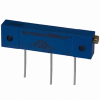
3059Y-1-500LF
Description
TRIMPOT 50 OHM 1.25"REC CER MT
Manufacturer
Bourns Inc.
Series
3059 - Sealedr
Specifications of 3059Y-1-500LF
Temperature Coefficient
±100ppm/°C
Resistance (ohms)
50
Termination Style
PC Pin
Power (watts)
1W
Tolerance
±10%
Number Of Turns
22
Adjustment Type
Side Adjustment
Resistive Material
Cermet
Mounting Type
Chassis Mount
Package / Case
Rectangular - 1.250" L x 0.190" W x 0.315" H (31.75mm x 4.83mm x 8.00mm)
Track Resistance
50ohm
No. Of Turns
22
Resistance Tolerance
± 10%
Power Rating
1W
Potentiometer Mounting
Through Hole
Resistance
50 Ohms
Operating Temperature Range
- 55 C to + 150 C
Element Type
Cermet
Dimensions
6.10 mm W x 31.75 mm L
Product
Trimmers
Taper
Linear
Rohs Compliant
Yes
Lead Free Status / RoHS Status
Lead free / RoHS Compliant
Lead Free Status / RoHS Status
Lead free / RoHS Compliant, Lead free / RoHS Compliant


Electrical Life............2,000 operations min.
Non-Switching Rating ......100 mA, 50 VDC
Switching Rating ................25 mA, 24 VDC
Contact Resistance (@ current 100 mA)
Insulation Resistance
Dielectric Strength ............500 VDC/minute
Capacitance .................5 pF max. between
Circuit ...................Single pole single throw
Mechanical Life
Operation Force .....................1000 gf max.
Stroke..............................................1.0 mm
Operating Temp. Range...-20 °C to +70 °C
Storage Temperature .......-40 °C to +85 °C
Vibration Test ......................MIL-STD-202F,
Shock Test ..........................MIL-STD-202F,
Base and Cover Materials
Actuator Materials..............................Nylon
Contact Materials ...................Alloy copper
Terminal Materials ..............................Brass
Contact Plating Materials ....3 micro inches
Terminal Plating Materials ...................Gold
Soldering Process............Vapor phase and
Standard Packaging
Specifications are subject to change without notice.
†
Customers should verify actual device performance in
their specific applications.
RoHS Directive 2002/95/EC Jan 27 2003 including Annex.
Electrical Characteristics
Environmental Characteristics
Physical Characteristics
Frequency .............10-55-10 Hz/1 minute
Directions ................X,Y,Z, three mutually
Time.....................2 hours each direction.
Gravity ..........50 G (peak value), 11 msec
Direction & Times ..................6 sides and
Color ................................................Black
Color................................................White
........100 megohms min. at 500 ±15 VDC
.....................2,000 operations per switch
.......................50 milliohms max. at initial
..UL94V-0 PPS plus glass fiber reinforced
.....IC tubes/all poles in the “off” position
gold plating over 40 micro inches nickel
IR-reflow soldering can be applied
100 milliohms max. after life test
per switch, 24 VDC, 25 mA
Method 213B, Condition A
plus glass fiber reinforced
3 times in each direction.
perpendicular directions
adjacent closed switch
High reliability
High reliability
Method 201A
REV 09/04
SDM Series – Surface Mount DIP Switch
Features
I
I
I
I
I
DIMENSIONS:
MM/(INCHES)
SCHEMATIC (TYP.)
1,2,3,4,5,6,7,8,9,10,12 POSITIONS AVAILABLE
SCHEMATIC (TYP.)
1,2,3,4,5,6,7,8,9,10 POSITIONS AVAILABLE
SDM Series
RECOMMENDED PCB LAYOUT
Product Dimensions
SDM Series Dimensions
SDM-12
SDM-10
SDM-8
SDM-6
SDM-4
SDM-2
(.043)
Model
1.1
Double contacts
Low contact resistance
Self-clean on contact area
Vapor phase solderable,
IR-reflow solderable
Terminal plating by gold gives
excellent results when soldering
(.028 ± .088)
No.
0.7 ± 0.2
(.386 ± .012)
SDMR SERIES
9.80 ± 0.3
(.069)
1.74
Pos.
(B±.004=.10X(P-1))
B±0.10=2.54X(P-1)
12
10
8
6
4
2
(A + .008/-0)
A + 0.2 / - 0
(.300 ± .010)
7.62 ± 0.25
0°~4°
B
(.020)
31.42
26.34
21.26
16.18
11.10
0.50
Dim.
6.02
(.100)
A
TYP.
2.54
(.118 + .004/-0)
3.0 + 0.10 / -0
(.028)
0.70
(.100)
TYP.
2.54
(.291)
(.244 = .008/-0)
7.40
6.20 + 0.2 / -0
SDMX SERIES
27.94
22.86
17.78
12.70
(.409)
Dim.
7.62
2.54
(.079)
10.4
(.028)
2.0
0.70
B
(.039)
1.0
MIN.
I
Model
Actuator
Number of Positions
Seal
Packaging Option
Packaging Specifications
How To Order
Reflow Soldering Profile
R = Tape and Reel Packaging (900 pcs./reel)
X = Raised
X = Standard (Not Sealed)
1 = 1 Position
2 = 2 Positions
3 = 3 Positions
4 = 4 Positions
5 = 5 Positions
6 = 6 Positions
T = Top Tape Sealed (“R” Actuator only)
(Top Sealed, Recessed Only)
275
225
175
125
(.061 ± .002)
1.55 ± 0.05
75
25
RoHS compliant
0
(.079 ± .006)
120 °C
DIA.
9, 10, 12
2.00 ± 0.15
(.157 ± .004)
4, 5, 6
4.00 ± 0.1
20
Pole
2, 3
7, 8
40
30-40 Sec.
(.630 ± .004)
16.00 ± 0.1
60
80-90 Sec.
10 = 10 Positions
12 = 12 Positions
R = Recessed
7 = 7 Positions
8 = 8 Positions
9 = 9 Positions
Time (Seconds)
80 100 120 140 160 180 200
†
10-15
Sec.
SDM R - 2 - T R
Tape Size (W)
16 mm
24 mm
32 mm
44 mm
(.079 ± .010)
2.00 ± 0.25
35-60
180 °C
Sec.
240 °C
DIA.
133
Related parts for 3059Y-1-500LF
Image
Part Number
Description
Manufacturer
Datasheet
Request
R

Part Number:
Description:
POT 500K OHM 1-1/4" RECT CERM MT
Manufacturer:
Bourns Inc.
Datasheet:
Part Number:
Description:
POT 100 OHM 1-1/4" RECT CERM MT
Manufacturer:
Bourns Inc.
Datasheet:
Part Number:
Description:
POT 10K OHM 1-1/4" RECT CERM MT
Manufacturer:
Bourns Inc.
Datasheet:
Part Number:
Description:
POT 100K OHM 1-1/4" RECT CERM MT
Manufacturer:
Bourns Inc.
Datasheet:
Part Number:
Description:
POT 1.0K OHM 1-1/4" RECT CERM MT
Manufacturer:
Bourns Inc.
Datasheet:
Part Number:
Description:
POT 50K OHM 1-1/4" RECT CERM MT
Manufacturer:
Bourns Inc.
Datasheet:
Part Number:
Description:
POT 2.0K OHM 1-1/4" RECT CERM MT
Manufacturer:
Bourns Inc.
Datasheet:
Part Number:
Description:
POT 200K OHM 1-1/4" RECT CERM MT
Manufacturer:
Bourns Inc.
Datasheet:
Part Number:
Description:
POT 20K OHM 1-1/4" RECT CERM MT
Manufacturer:
Bourns Inc.
Datasheet:
Part Number:
Description:
POT 1.0M OHM 1-1/4" RECT CERM MT
Manufacturer:
Bourns Inc.
Datasheet:

Part Number:
Description:
Manufacturer:
Bourns, Inc.
Datasheet:
Part Number:
Description:
11mm Potentiometer
Manufacturer:
Bourns, Inc.
Datasheet: