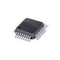
FCM8202QY Fairchild Semiconductor, FCM8202QY Datasheet - Page 11

FCM8202QY
Manufacturer Part Number
FCM8202QY
Description
Motor / Motion / Ignition Controllers & Drivers 3-Phase Sinusoidal Brushless DC Motor
Manufacturer
Fairchild Semiconductor
Type
3-Phase Sinusoidal Brushless DC Motor Controllerr
Datasheet
1.FCM8202QY.pdf
(13 pages)
Specifications of FCM8202QY
Product
Fan / Motor Controllers / Drivers
Operating Supply Voltage
0 V to 30 V
Supply Current
5 mA
Mounting Style
SMD/SMT
Package / Case
LQFP-32
Operating Temperature
- 40 C to + 85 C
Lead Free Status / RoHS Status
Lead free / RoHS Compliant
Available stocks
Company
Part Number
Manufacturer
Quantity
Price
Company:
Part Number:
FCM8202QY
Manufacturer:
Fairchild Semiconductor
Quantity:
10 000
Part Number:
FCM8202QY
Manufacturer:
FAIRCHILD/仙童
Quantity:
20 000
Part Number:
FCM8202QYD
Manufacturer:
FAIRCHILD/仙童
Quantity:
20 000
© 2010 Fairchild Semiconductor Corporation
FCM8202 • Rev. 1.0.0
Current Feedback and Protections
The current feedback circuit performs two major
functions: (1) for generating a current feedback signal
for the motor control (2) for the over-current protection.
The I_IN pin outputs 50µA current to provide a DC bias
on the I_IN terminal to prevent a negative voltage.
Equation 1 shows the I_FB and the I_IN. A 0.5V DC
bias on I_IN is recommended. The maximum average
current signal is 1V. By using these parameters, the
maximum I_FB signal swing is 0.5V~4.5V.
Protections and Faults
Table 2. Faults Table
V
I
_
FB
Figure 18. Sine-Wave Output at CW=0
=
OC_Latch
Hall Error
V
SHORT
V
V
(
HOVP
Type
V
OUT
PP
PP
OS
RT
S
OV
UV
×
UV
) 8
+
(
I
BIAS
_
I
_
IN
×
R
Free, Reset
BIAS
State
Free
Free
Free
Free
Free
Free
Free
Free
)
(1)
11
FCM8202
protection (OCP). The first level is 1.4V, is used for
overload current protection with the OCP timer delay. If
the I_IN is higher than 1.4V, the OC timer is triggered.
The OC_Latch is enabled once the timer is exceeds its
time-out limit. The second level is 1.5V, used for the
cycle-by-cycle current limit. The PWM signal is turned
off immediately when the I_IN is > 1.5V. The third level
is 2.5V, designed for short-circuit protection. If the I_IN
is > 2.5V for over three PWM pulses, all PWM outputs
(U, V, W, X, Y, Z pins) are turned off.
Hall = 000 or 111
Open and Short
V
I_IN > 1.4V
I_IN > 2.5V
SENSE
V
V
R
Trigger
V
PP
OUT
T
PP
Figure 19. Current Feedback Flow
< 1.0V
> 18V
< 8V
provides
< 4V
> 4.5V
three
levels
V
FREE/nST
FREE/nST
FREE/nST
V
SENSE
V
R
Release
V
OUT
PP
T
PP
of
> 1.2V
< 17V
> 4.5V
> 9V
< 4.0V
over-current
www.fairchildsemi.com


