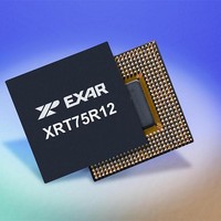
XRT75R12IB-F Exar Corporation, XRT75R12IB-F Datasheet - Page 11

XRT75R12IB-F
Manufacturer Part Number
XRT75R12IB-F
Description
Peripheral Drivers & Components (PCIs) 12 Channel 3.3V-5V temp -45 to 85C
Manufacturer
Exar Corporation
Datasheet
1.XRT75R12IB-F.pdf
(90 pages)
Specifications of XRT75R12IB-F
Maximum Operating Temperature
+ 85 C
Minimum Operating Temperature
- 40 C
Mounting Style
SMD/SMT
Operating Supply Voltage
3.3 V
Package / Case
TBGA-420
Ic Interface Type
Parallel, Serial
Supply Voltage Range
3.135V To 3.465V
Operating Temperature Range
-40°C To +85°C
Digital Ic Case Style
BGA
No. Of Pins
420
Filter Terminals
SMD
Rohs Compliant
Yes
Data Rate Max
51.84Mbps
Lead Free Status / RoHS Status
Lead free / RoHS Compliant
RECEIVE LINE SIDE PINS
REV. 1.0.4
AE22
AE18
AC13
AD22
AD18
AE14
AD13
P
AF14
AE9
AE5
AD9
AD5
B22
B18
A14
D13
C22
C18
B14
C13
B9
B5
C9
C5
IN
#
S
IGNAL
RRing10
RRing11
RRing0
RRing1
RRing2
RRing3
RRing4
RRing5
RRing6
RRing7
RRing8
RRing9
RTip10
RTip11
RTip0
RTip1
RTip2
RTip3
RTip4
RTip5
RTip6
RTip7
RTip8
RTip9
TWELVE CHANNEL E3/DS3/STS-1 LINE INTERFACE UNIT WITH JITTER ATTENUATOR
N
AME
T
YPE
I
I
Receive TIP Input
These input pins along with the corresponding RRing_n input pin function as the
Receive DS3/E3/STS-1 Line input signal for a given channel of the XRT75R12.
Cconnect this signal and the corresponding RRING_n input signal to a 1:1
transformer.
Whenever the RTIP/RRING input pins are receiving a positive-polarity pulse
within the incoming DS3, E3 or STS-1 line signal, this input pin will be pulsed to
a higher voltage than its corresponding RRING_n input pin.
Conversely, whenever the RTIP/RRING input pins are receiving a negative-
polarity pulse within the incoming DS3, E3 or STS-1 line signal, this input pin
will be pulsed to a lower voltage than its corresponding RRING_n input pin.
Receive Ring Input
These input pins along with the corresponding RTIP_n input pin function as the
Receive DS3/E3/STS-1 Line input signal for a given channel of the XRT75R12.
Connect this signal and the corresponding RTIP_n input signal to a 1:1 trans-
former. (See Figure 6)
Whenever the RTIP/RRING input pins are receiving a positive-polarity pulse
within the incoming DS3, E3 or STS-1 line signal, then this input pin will be
pulsed to a lower voltage than its corresponding RTIP_n input pin.
Conversely, whenever the RTIP/RRING input pins are receiving a negative-
polarity pulse within the incoming DS3, E3 or STS-1 line signal, then this input
pin will be pulsed to a higher voltage than its corresponding RTIP_n input pin.
8
D
ESCRIPTION
XRT75R12


