DFB2060 Fairchild Semiconductor, DFB2060 Datasheet
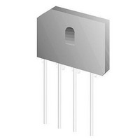
Bridge Rectifiers 600V 20A Glass Pass. Bridge Rectifier

DFB2060

Manufacturer Part Number
DFB2060
Description
Bridge Rectifiers 600V 20A Glass Pass. Bridge Rectifier
Manufacturer
Fairchild Semiconductor
Datasheet

Specifications of DFB2060

Peak Reverse Voltage
600 V
Maximum Rms Reverse Voltage
420 V
Forward Continuous Current
20 A
Max Surge Current
250 A
Forward Voltage Drop
1.1 V
Maximum Operating Temperature
+ 125 C
Mounting Style
Through Hole
Minimum Operating Temperature
- 55 C
Package / Case
TS-6P
Lead Free Status / RoHS Status
Lead free / RoHS Compliant
© 2010 Fairchild Semiconductor Corporation
DFB2005 - DFB20100 Rev. A2
DFB2005 - DFB20100
Glass Passivated Bridge Rectifiers
Features
• UL certificate # E326243
• Glass passivated junction
• Ideal for printed circuit board
• Reliable low cost construction
• Plastic material has Underwriters Laboratory Flammability Classification 94V-0
• Surge overload rating to 250 amperes peak
• High case dielectric strength of 2000 V
• Isolated voltage from case to lead over 2500 volts
Absolute Maximum Ratings*
* Single phase, half wave, 60Hz, resistive or inductive load. For capacitive load, derate current by 20%
** Device mounted on 4" x 5" x 0.25" Al-plate heat sink.
*** In development. Please contact Fairchild Semiconductor for more information.
Electrical Characteristics
* Measured at 1MHz and applied Reverse bias of 4.0V DC.
Symbol
Symbol
V
V
T
R
I
V
I
FSM
(AV)
RRM
RMS
V
T
STG
I
I
Cj
θJC
DC
2
R
F
J
t
Maximum
Recurrent Peak Reverse Voltage
Maximum RMS Voltage
Maximum DC Blocking Voltage
Maximum
Average Forward Rectified Current
Peak Forward Surge Current
(8.3mS Single Half-wave)
Typical Thermal Resistance**
Operating Temperature Range
Storage Temperature Range
Maximum
Instantaneous Forward Voltage
Maximum DC Reverse Current
at Rated DC Blocking Voltage
Rating for fusing (t < 8.3mS)
Typical Junction Capacitance per leg*
Parameter
Parameter
T
A
= 25°C unless otherwise specified
RMS
T
A
= 25°C unless otherwise noted
DFB20
@ 10A
@ 20A
@ T
@ T
05***
50
35
50
A
A
Test condition
= 25°C
= 125°C
DFB20
1
10***
100
100
70
DFB20
20***
200
140
200
-55 to +150
-55 to +150
DFB20
Value
40***
280
400
400
250
0.8
20
DFB20
600
420
600
60
Value
500
259
140
1.0
1.1
10
DFB20
80***
800
560
800
+ ~
TS-6P
~
-
DFB20
100***
1000
1000
700
www.fairchildsemi.com
July 2010
Units
°C/W
Unit
A
µA
°C
°C
pF
V
V
V
A
A
V
2
S

Related parts for DFB2060

DFB2060 Summary of contents

Page 1

... Operating Temperature Range J T Storage Temperature Range STG * Single phase, half wave, 60Hz, resistive or inductive load. For capacitive load, derate current by 20% ** Device mounted on 4" x 5" x 0.25" Al-plate heat sink. *** In development. Please contact Fairchild Semiconductor for more information. Electrical Characteristics Symbol Parameter Maximum V F ...

Page 2

... Typical Performance Characteristics Figure 1. Maximum Derating Curve for Output Current Figure 3. Typical Reverse Characteristics per Leg Figure 5. Typical Junction Capacitance © 2010 Fairchild Semiconductor Corporation DFB2005 - DFB20100 Rev. A2 Figure 2. Maximum Forward Surge Current per Leg Figure 4. Typical Forward Characteristics per Leg 2 www ...

Page 3

... Physical Dimensions © 2010 Fairchild Semiconductor Corporation DFB2005 - DFB20100 Rev. A2 TS-6P 3 Dimensions in Millimeters www.fairchildsemi.com ...

Page 4

... TRADEMARKS The following includes registered and unregistered trademarks and service marks, owned by Fairchild Semiconductor and/or its global subsidiaries, and is not intended exhaustive list of all such trademarks. AccuPower F-PFS FRFET Auto-SPM Build it Now Global Power Resource CorePLUS Green FPS CorePOWER Green FPS ...

Related keywords