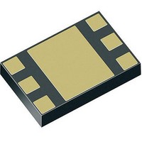
BGA 751L7 E6327 Infineon Technologies, BGA 751L7 E6327 Datasheet - Page 7

BGA 751L7 E6327
Manufacturer Part Number
BGA 751L7 E6327
Description
RF Amplifier RF SILICON MMIC
Manufacturer
Infineon Technologies
Type
Single Band Low Noise Amplifierr
Datasheet
1.BGA_751L7_E6327.pdf
(22 pages)
Specifications of BGA 751L7 E6327
Mounting Style
SMD/SMT
Operating Frequency
800 MHz to 900 MHz
Noise Figure
1.05 dB
Operating Supply Voltage
2.6 V to 3 V
Supply Current
3.3 mA, 0.5 mA
Maximum Operating Temperature
+ 85 C
Minimum Operating Temperature
- 30 C
Package / Case
TSLP-7-1
Lead Free Status / RoHS Status
Lead free / RoHS Compliant
Other names
BGA751L7E6327XT
2.4
Table 4
Parameter
Supply voltage
Supply current high gain
mode
Supply current low gain
mode
Supply current standby
mode
Logic level high
Logic level low
Logic currents VEN
Logic currents VGS
2.5
Table 5
Control Voltage
VEN
H
H
L
L
1) In order to achieve minimum standby current it is encouraged to apply logic low-level at the VGS pin in standby mode
2.6
Table 6
Parameter
Settling time gainstep
Data Sheet
although this is not mandatory. Details see section 2.4.
DC Characteristics
DC Characteristics,
Gain Mode Select Truth Table
Truth Table
Switching Times
Typical switching times;
VGS
L
H
L
H
Symbol
V
I
I
I
V
V
I
I
I
I
CCHG
CCLG
CCOFF
ENL
ENH
GSL
GSH
CC
HI
LO
Symbol
t
GS
T
A
= 25 °C
T
Min.
2.6
1.5
-0.2
A
= -30 ... 85 °C
Min.
BGA751L7 - Low Power Single-Band UMTS LNA
Typ.
2.8
3.3
500
0.1
2.8
0.0
5.0
5.0
Values
Bands V, VI and VIII
State
HG
OFF
ON
STANDBY
Typ.
1
7
Values
Max.
3.0
2.0
0.5
0.1
6.0
0.1
6.0
1)
Max.
Unit
V
mA
µA
µA
V
V
µA
µA
µA
µA
Unit
µs
Note / Test Condition
VEN and VGS
VEN
VGS
LG
ON
OFF
Electrical Characteristics
Note / Test Condition
Switching LG ↔ HG
DC Characteristics
V3.2, 2009-05-27


