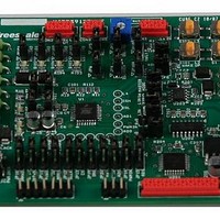
KIT33912EVME Freescale Semiconductor, KIT33912EVME Datasheet - Page 37

KIT33912EVME
Manufacturer Part Number
KIT33912EVME
Description
MCU, MPU & DSP Development Tools For MC33912 RS-232 SPI
Manufacturer
Freescale Semiconductor
Datasheet
1.KIT33912EVME.pdf
(50 pages)
Specifications of KIT33912EVME
Processor To Be Evaluated
MC33912
Interface Type
RS-232, SPI
Operating Supply Voltage
12 V
Lead Free Status / RoHS Status
Lead free / RoHS Compliant
9.6
The MC33912 device, including two 60mA High Side Switches and two 150mA Low Side Switches with output protection, are
available for driving resistive and inductive loads. The interconnection of the MC33912 device with an output connector is shown
in
9.7
The MC33912 device has four high voltage inputs available for use in contact monitoring or as external wake-up inputs. The
terminals can be used as high voltage analogue inputs. For the L2, L3, L4 inputs, 33k ohm series resistors are used between the
connector and the device pins. L1 input is directly linked to the connector. Refer to
9.8
Connector CON4 is linked to the MCU pins, not used in the application. The connector includes a Hall sensor supply terminal,
ground and a +5V output supply terminal. See
Freescale Semiconductor
Table
9-5.
CON2 HSx LSx Outputs
CON3 Lx Inputs
CON4 The MCU Input Output Pins
Terminal
Terminal
Terminal
KIT33912EVME System Basis Chip with LIN Tranceiver Setup Instructions, Rev. 2.0
1
2
3
4
5
6
1
2
1
2
3
4
5
6
Table 9-5. CON2 Output Connector Pin Definitions
Table 9-6. CON3 Output Input Terminal Definitions
Table 9-7. MCU Pins not used in the Application
Terminal Name
Terminal Name
Terminal Name
PGND
PGND
HVDD
PGND
PGND
PTD0
HS1
HS2
LS1
LS2
L1
L2
L3
L4
Table
9-7.
Hall sensor switchable supply terminal.
Not used in application.
High Side Switch output HS1.
High Side Switch output HS2.
Power ground.
Low Side Switch output LS1.
Low Side Switch output LS1.
Power ground.
Power ground.
L1 terminal is a wake-up capable digital input. In
addition, can be sensed as analogue via the
analogue multiplexer.
L2 terminal is a wake-up capable digital input. In
addition, can be sensed as analogue via the
analogue multiplexer.
L3 terminal is a wake-up capable digital input. In
addition, can be sensed analogue via the
analogue multiplexer.
L4 terminal is a wake-up capable digital input. In
addition, can be sensed analogue via the
analogue multiplexer.
Power ground.
Definition
Definition
Definition
Table
9-6.
Interconnect Board Description
29


