KIT33912EVME Freescale Semiconductor, KIT33912EVME Datasheet - Page 35
KIT33912EVME
Manufacturer Part Number
KIT33912EVME
Description
MCU, MPU & DSP Development Tools For MC33912 RS-232 SPI
Manufacturer
Freescale Semiconductor
Datasheet
1.KIT33912EVME.pdf
(50 pages)
Specifications of KIT33912EVME
Processor To Be Evaluated
MC33912
Interface Type
RS-232, SPI
Operating Supply Voltage
12 V
Lead Free Status / RoHS Status
Lead free / RoHS Compliant


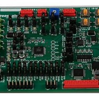
Chapter 9 Interconnect Board Description
9.1
This chapter gives a basic description of the Interconnect Board. The following sections provide the basic information:
9.2
The RS232 connector J1 allows connection to a PC.
9.3
The MCU contains a single wire background debug interface that supports in-circuit programming of on-chip nonvolatile memory
and sophisticated non-intrusive debug capabilities.
Freescale Semiconductor
•
•
•
•
•
•
•
•
Overview
9.2, J1 RS232
9.3, J201 Background Debug Mode (BDM)
9.4, J3 External Control
9.5, CON1 LIN Bus Connector
9.6, CON2 HSx LSx Outputs
9.7, CON3 Lx Inputs
9.8, CON4 The MCU Input Output Pins
9.9, CON5 ISENSE Inputs
J1 RS232
J201 Background Debug Mode (BDM)
Terminal
Terminal
KIT33912EVME System Basis Chip with LIN Tranceiver Setup Instructions, Rev. 2.0
1
2
3
4
5
6
7
8
9
Table 9-1. J1 Serial Peripheral Interface Terminal Definitions
1
2
3
4
5
6
Table 9-2. J201 Program Debug Terminal Definition
Terminal Name
Terminal Name
Not used
Not used
Not used
RESET
BKGD
RXD
TXD
GND
GND
VDD
NC
NC
NC
NC
NC
Table 9-2
Table 9-1
Carrier detect.
Transmit data from MCU to PC.
Received data from PC to MCU.
Data terminal ready.
Ground.
Data set ready, Carrier detect.
No connect.
No connect.
No connect.
Background debug.
Ground.
No connect.
Reset.
No connect.
+5V voltage supply.
shows the standard definition for a 6 pin connector.
shows the terminal definitions for the J1 connector.
Definition
Definition
Interconnect Board Description
27
Related parts for KIT33912EVME
Image
Part Number
Description
Manufacturer
Datasheet
Request
R

Part Number:
Description:
Manufacturer:
Freescale Semiconductor, Inc
Datasheet:
Part Number:
Description:
Manufacturer:
Freescale Semiconductor, Inc
Datasheet:
Part Number:
Description:
Manufacturer:
Freescale Semiconductor, Inc
Datasheet:
Part Number:
Description:
Manufacturer:
Freescale Semiconductor, Inc
Datasheet:
Part Number:
Description:
Manufacturer:
Freescale Semiconductor, Inc
Datasheet:
Part Number:
Description:
Manufacturer:
Freescale Semiconductor, Inc
Datasheet:
Part Number:
Description:
Manufacturer:
Freescale Semiconductor, Inc
Datasheet:
Part Number:
Description:
Manufacturer:
Freescale Semiconductor, Inc
Datasheet:
Part Number:
Description:
Manufacturer:
Freescale Semiconductor, Inc
Datasheet:
Part Number:
Description:
Manufacturer:
Freescale Semiconductor, Inc
Datasheet:
Part Number:
Description:
Manufacturer:
Freescale Semiconductor, Inc
Datasheet:
Part Number:
Description:
Manufacturer:
Freescale Semiconductor, Inc
Datasheet:
Part Number:
Description:
Manufacturer:
Freescale Semiconductor, Inc
Datasheet:
Part Number:
Description:
Manufacturer:
Freescale Semiconductor, Inc
Datasheet:
Part Number:
Description:
Manufacturer:
Freescale Semiconductor, Inc
Datasheet: