KIT33912EVME Freescale Semiconductor, KIT33912EVME Datasheet - Page 15
KIT33912EVME
Manufacturer Part Number
KIT33912EVME
Description
MCU, MPU & DSP Development Tools For MC33912 RS-232 SPI
Manufacturer
Freescale Semiconductor
Datasheet
1.KIT33912EVME.pdf
(50 pages)
Specifications of KIT33912EVME
Processor To Be Evaluated
MC33912
Interface Type
RS-232, SPI
Operating Supply Voltage
12 V
Lead Free Status / RoHS Status
Lead free / RoHS Compliant


2.3
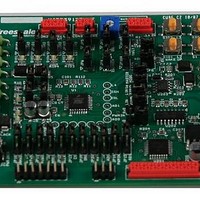
To run an embedded application code, the KIT33912EVME must be configured by Jumpers. Follow the steps to configure the
board.
Freescale Semiconductor
Supply Jumpers
1.
2.
3.
4.
5.
6.
Results: The MC33912 device is in Normal Mode.
Quick System Setup to Run the SBCLIN Evaluation Module
Displace unnecessary connectors.
a)
b)
To supply the devices, place the following Jumpers.
a)
b)
c)
For communication from the MCU to a personal computer, through FreeMASTER protocol, place Jumpers JP202
(TxD) and JP203 (RxD) in positions 1-2, which connect the MCU and the TTL / RS232 converter.
Configure the KIT33912EVME to an on-board control, by ensuring that Jumpers JP10 - JP16 and JP19 - JP20 are in
position 1-2.
Connect the PC interface to the host PC by connecting the RS232 cable to connector J1 (RS-232) on the PC interface
and to a serial port (COM) on the host PC.
Connect the 12 V power supply.
Power Supply 12V
Disconnect the programming header J201 (BKGD).
Disconnect the LIN connector CON1 (LIN).
Place Jumper JP9 (VS1) to supply the MC33912 device.
Place Jumper JP8 (VS2) to supply the High Side Switches in the MC33912 device.
Place Jumper JP7 (VDD) to supply the MCU from an Internal Voltage Regulator.
KIT33912EVME System Basis Chip with LIN Tranceiver Setup Instructions, Rev. 2.0
on-board Control Jumpers
Figure 2-4. SBCLIN Power-Up Quick Guide
TTL / LIN - RS232 Jumpers
Connector RS232
Communication
Setup Instructions
7
Related parts for KIT33912EVME
Image
Part Number
Description
Manufacturer
Datasheet
Request
R

Part Number:
Description:
Manufacturer:
Freescale Semiconductor, Inc
Datasheet:
Part Number:
Description:
Manufacturer:
Freescale Semiconductor, Inc
Datasheet:
Part Number:
Description:
Manufacturer:
Freescale Semiconductor, Inc
Datasheet:
Part Number:
Description:
Manufacturer:
Freescale Semiconductor, Inc
Datasheet:
Part Number:
Description:
Manufacturer:
Freescale Semiconductor, Inc
Datasheet:
Part Number:
Description:
Manufacturer:
Freescale Semiconductor, Inc
Datasheet:
Part Number:
Description:
Manufacturer:
Freescale Semiconductor, Inc
Datasheet:
Part Number:
Description:
Manufacturer:
Freescale Semiconductor, Inc
Datasheet:
Part Number:
Description:
Manufacturer:
Freescale Semiconductor, Inc
Datasheet:
Part Number:
Description:
Manufacturer:
Freescale Semiconductor, Inc
Datasheet:
Part Number:
Description:
Manufacturer:
Freescale Semiconductor, Inc
Datasheet:
Part Number:
Description:
Manufacturer:
Freescale Semiconductor, Inc
Datasheet:
Part Number:
Description:
Manufacturer:
Freescale Semiconductor, Inc
Datasheet:
Part Number:
Description:
Manufacturer:
Freescale Semiconductor, Inc
Datasheet:
Part Number:
Description:
Manufacturer:
Freescale Semiconductor, Inc
Datasheet: