EVL6563S-200ZRC STMicroelectronics, EVL6563S-200ZRC Datasheet - Page 36
EVL6563S-200ZRC
Manufacturer Part Number
EVL6563S-200ZRC
Description
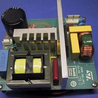
Power Management Modules & Development Tools Tranisition Mode PFC L6563S EVL Board
Manufacturer
STMicroelectronics
Type
Motor / Motion Controllers & Driversr
Datasheet
1.EVL6563S-200ZRC.pdf
(39 pages)
Specifications of EVL6563S-200ZRC
Product
Power Management Modules
Lead Free Status / RoHS Status
Lead free / RoHS Compliant


Appendix B
36/39
Measuring transformer and coupled inductor parameters
From a practical point of view there is the need to measure the parameters of coupled
inductors (transformers) L
circuits. Needless to say that it is of particular interest to obtain the parameters of the
“physical model” with a = n , L
L
be done. The best way to proceed is to use a Z-meter, taking the measurements at a low
enough frequency that the parasitic capacitance of the windings can be neglected. There
are two basic methods to completely characterize a coupled inductor or a transformer from
the electrical point of view: the open/short-circuit inductance (OS) method and the series-
aiding/opposing inductance (AO) method.
According to the OS method, three measurements are taken:
●
●
●
Through inspection of
measurement:
Equation 30
M is determined using (A2):
Equation 31
Measuring L
to unity. It is not recommended when the winding resistance is not negligible.
The AO method is based on the fact that by connecting the two windings in series their
combined inductance is given by L
way the windings are connected, as shown in
thereby equal to 4M.
According to the AO method, four measurements are taken:
●
●
●
●
1
and L
The primary inductance with the secondary open (L
The primary inductance with the secondary shorted (L
The secondary inductance with the primary open (L
The primary inductance with the secondary open (L
The secondary inductance with the primary open (L
The combined inductance with series-aiding connection (L
The combined inductance with series-opposing connection (L
2
are directly measurable. To determine M or k appropriate measurements need to
1s
Measuring transformer and coupled inductor
parameters
accurately might be an issue, and so this method is suitable when k is close
Figure 29
1
, L
L
M
2
s 1
Doc ID 17273 Rev 1
, L
and M or, equivalently, k, and derive those of the equivalent
it is very easy to derive the coupling coefficient from the L
=
l1
L
1
and L
1
+ L
(
1
−
2
M =
k
± 2M, where the sign given to 2M depends on the
l2
2
.
)
k
Figure 30
⇒
L
1
L
2
k
=
. The difference of the two values is
1
1
2
1
2
)
).
−
)
)
1s
L
L
s 1
)
1
A
)
O
).
AN3180
1s
Related parts for EVL6563S-200ZRC
Image
Part Number
Description
Manufacturer
Datasheet
Request
R

Part Number:
Description:
EVAL BOARD FOR L6563(100W)
Manufacturer:
STMicroelectronics
Datasheet:

Part Number:
Description:
EVAL BOARD FOR L6563(250W)
Manufacturer:
STMicroelectronics
Datasheet:

Part Number:
Description:
EVAL BOARD FOR L6563(400W)
Manufacturer:
STMicroelectronics
Datasheet:

Part Number:
Description:
STMicroelectronics [RIPPLE-CARRY BINARY COUNTER/DIVIDERS]
Manufacturer:
STMicroelectronics
Datasheet:
Part Number:
Description:
STMicroelectronics [LIQUID-CRYSTAL DISPLAY DRIVERS]
Manufacturer:
STMicroelectronics
Datasheet:

Part Number:
Description:
BOARD EVAL FOR MEMS SENSORS
Manufacturer:
STMicroelectronics
Datasheet:
Part Number:
Description:
NPN TRANSISTOR POWER MODULE
Manufacturer:
STMicroelectronics
Datasheet:
Part Number:
Description:
TURBOSWITCH ULTRA-FAST HIGH VOLTAGE DIODE
Manufacturer:
STMicroelectronics
Datasheet:
Part Number:
Description:
Manufacturer:
STMicroelectronics
Datasheet:
Part Number:
Description:
DIODE / SCR MODULE
Manufacturer:
STMicroelectronics
Datasheet:
Part Number:
Description:
DIODE / SCR MODULE
Manufacturer:
STMicroelectronics
Datasheet:
Part Number:
Description:
Search -----> STE16N100
Manufacturer:
STMicroelectronics
Datasheet: