EVL6563S-200ZRC STMicroelectronics, EVL6563S-200ZRC Datasheet - Page 5
EVL6563S-200ZRC
Manufacturer Part Number
EVL6563S-200ZRC
Description
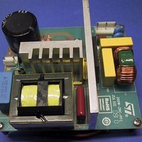
Power Management Modules & Development Tools Tranisition Mode PFC L6563S EVL Board
Manufacturer
STMicroelectronics
Type
Motor / Motion Controllers & Driversr
Datasheet
1.EVL6563S-200ZRC.pdf
(39 pages)
Specifications of EVL6563S-200ZRC
Product
Power Management Modules
Lead Free Status / RoHS Status
Lead free / RoHS Compliant


AN3180
Basic topologies with zero-ripple current
All converter topologies are capable of producing zero-ripple current phenomenon, provided
there are two or more inductors which have equal (or, more generally, proportional) voltages
of equal frequency and phase. Some topologies, such as Cuk and SEPIC, have two
inductors, which can be coupled on a common magnetic core: so they immediately lend
themselves to ripple-steering. The other basic topologies - buck, boost, buck-boost, flyback
and single-output forward - have typically a single inductor and then, to reduce its ripple
current to zero, they must be modified with the addition of a second winding wound on the
same inductor core. Moreover, this additional winding must be connected in such a way as
to have the same voltage as the winding where the ripple current is to be cancelled.
Figure 2
shows examples of how to modify some of the basic topologies to achieve zero-
ripple inductor current, to have non-pulsating current at either the input or the output. In all
examples it is possible to recognize the addition of a cell, a two-port circuit commonly
termed a smoothing transformer and shown separately in
Figure
3. This cell is able to divert,
or steer, the AC component (the ripple current) from the externally accessible DC winding,
to the AC winding (cancellation winding) whose current conduction path goes directly to the
input port, leaving only DC current flowing through the DC winding and the output port. Note
that the denomination of input and output ports of the smoothing transformer cell is different
from that of input and output of the converter where the cell is applied.
Figure 3.
Smoothing transformer and related currents
This application note, after reviewing the theoretical base, considers the realization of zero-
ripple inductor current to minimize the input ripple in a TM PFC pre-regulator. In these
systems, the large input ripple is one of the major limitations to its use at higher power
levels.
Doc ID 17273 Rev 1
5/39
Related parts for EVL6563S-200ZRC
Image
Part Number
Description
Manufacturer
Datasheet
Request
R

Part Number:
Description:
EVAL BOARD FOR L6563(100W)
Manufacturer:
STMicroelectronics
Datasheet:

Part Number:
Description:
EVAL BOARD FOR L6563(250W)
Manufacturer:
STMicroelectronics
Datasheet:

Part Number:
Description:
EVAL BOARD FOR L6563(400W)
Manufacturer:
STMicroelectronics
Datasheet:

Part Number:
Description:
STMicroelectronics [RIPPLE-CARRY BINARY COUNTER/DIVIDERS]
Manufacturer:
STMicroelectronics
Datasheet:
Part Number:
Description:
STMicroelectronics [LIQUID-CRYSTAL DISPLAY DRIVERS]
Manufacturer:
STMicroelectronics
Datasheet:

Part Number:
Description:
BOARD EVAL FOR MEMS SENSORS
Manufacturer:
STMicroelectronics
Datasheet:
Part Number:
Description:
NPN TRANSISTOR POWER MODULE
Manufacturer:
STMicroelectronics
Datasheet:
Part Number:
Description:
TURBOSWITCH ULTRA-FAST HIGH VOLTAGE DIODE
Manufacturer:
STMicroelectronics
Datasheet:
Part Number:
Description:
Manufacturer:
STMicroelectronics
Datasheet:
Part Number:
Description:
DIODE / SCR MODULE
Manufacturer:
STMicroelectronics
Datasheet:
Part Number:
Description:
DIODE / SCR MODULE
Manufacturer:
STMicroelectronics
Datasheet:
Part Number:
Description:
Search -----> STE16N100
Manufacturer:
STMicroelectronics
Datasheet: