EVL6563S-200ZRC STMicroelectronics, EVL6563S-200ZRC Datasheet - Page 17
EVL6563S-200ZRC
Manufacturer Part Number
EVL6563S-200ZRC
Description
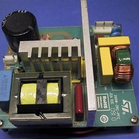
Power Management Modules & Development Tools Tranisition Mode PFC L6563S EVL Board
Manufacturer
STMicroelectronics
Type
Motor / Motion Controllers & Driversr
Datasheet
1.EVL6563S-200ZRC.pdf
(39 pages)
Specifications of EVL6563S-200ZRC
Product
Power Management Modules
Lead Free Status / RoHS Status
Lead free / RoHS Compliant


AN3180
bobbin, unless mounting clips or gluing are used (quite impractical to use during the cut-
and-try phase). The position of the core inside the bobbin, especially along the direction of
the legs, is critical because it changes the position of the air gap with respect to the
windings. Moving the core causes significant variations of the magnetizing inductance,
therefore it is recommended to fix the cores in a stable position as close as possible to that
of the finished sample before doing any inductance measurement or test on the converter
circuit.
It is now important to determine how much spread can be expected in mass production.
Side-by-side winding arrangements in slotted bobbins are quite commonly used when
making common-mode chokes. For wires which are not too thin (say, above 0.2 mm) with a
good winding machine it is not difficult to have a tolerance of around 4-5 % on the leakage
inductance. As for the self-inductance of one winding, using gapped cores the tolerance on
the AL factor (nH/turn
>0.1mm for small cores (e.g. an E30/15/7) and for air gaps >0.4 mm in case of bigger cores
(e.g. an E55/28/21). An additional 3 % tolerance has to be typically considered due to the
above mentioned displacement of the core inside the bobbin. It is therefore possible to
assume 5 % tolerance for L
Turn ratio n is not subject to production spread, the rounding error just introduces a fixed
mismatch in the zero-ripple current condition. Again, using gapped cores, where the air gap
cannot be adjusted to compensate for the mismatch, the rounding error is 0.5 turns,
therefore the maximum absolute error that it introduces on n is ≤ 0.5/N
relative error is (0.5/N
With some simple algebraic manipulations it is possible to find the relative error on the zero-
ripple current condition in
respectively:
Equation 18
As n is slightly greater than 1 the effect of the spread of L
example, with n =1.3, the resulting maximum spread is δ = -4.2 % to +3.6 %.
With good approximation, it is possible to consider that this tolerance band is centered on a
value shifted by the rounding error. Referring to
more quickly for negative values, therefore it is better to round N
provide a “positive offset” to δ and be in a region where A changes less. Furthermore, if
N
%, +4.6 %.
2
=50 turns (rounded up), the rounding error is +1 %, so that the total tolerance band is -3.2
2
1
), deducible from ferrite core catalogs, is 5 % or better for air gaps
)/n = 0.5/N
Equation 7
l1
and 8 % tolerance on L
Doc ID 17273 Rev 1
2
.
δ
due to the spread δ
=
(
n
−
1
)
Zero-ripple current phenomenon: practice
δ
Figure 7
1
1
+
−
δ
δ
1
l
1
1
.
, the attenuation factor A degrades
l1
l1
and L1 is attenuated. For
and δ
2
1
to the upper integer, to
of L
1
l1
and the maximum
and L
1
,
17/39
Related parts for EVL6563S-200ZRC
Image
Part Number
Description
Manufacturer
Datasheet
Request
R

Part Number:
Description:
EVAL BOARD FOR L6563(100W)
Manufacturer:
STMicroelectronics
Datasheet:

Part Number:
Description:
EVAL BOARD FOR L6563(250W)
Manufacturer:
STMicroelectronics
Datasheet:

Part Number:
Description:
EVAL BOARD FOR L6563(400W)
Manufacturer:
STMicroelectronics
Datasheet:

Part Number:
Description:
STMicroelectronics [RIPPLE-CARRY BINARY COUNTER/DIVIDERS]
Manufacturer:
STMicroelectronics
Datasheet:
Part Number:
Description:
STMicroelectronics [LIQUID-CRYSTAL DISPLAY DRIVERS]
Manufacturer:
STMicroelectronics
Datasheet:

Part Number:
Description:
BOARD EVAL FOR MEMS SENSORS
Manufacturer:
STMicroelectronics
Datasheet:
Part Number:
Description:
NPN TRANSISTOR POWER MODULE
Manufacturer:
STMicroelectronics
Datasheet:
Part Number:
Description:
TURBOSWITCH ULTRA-FAST HIGH VOLTAGE DIODE
Manufacturer:
STMicroelectronics
Datasheet:
Part Number:
Description:
Manufacturer:
STMicroelectronics
Datasheet:
Part Number:
Description:
DIODE / SCR MODULE
Manufacturer:
STMicroelectronics
Datasheet:
Part Number:
Description:
DIODE / SCR MODULE
Manufacturer:
STMicroelectronics
Datasheet:
Part Number:
Description:
Search -----> STE16N100
Manufacturer:
STMicroelectronics
Datasheet: