EVL6563S-200ZRC STMicroelectronics, EVL6563S-200ZRC Datasheet - Page 15
EVL6563S-200ZRC
Manufacturer Part Number
EVL6563S-200ZRC
Description
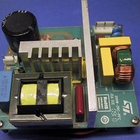
Power Management Modules & Development Tools Tranisition Mode PFC L6563S EVL Board
Manufacturer
STMicroelectronics
Type
Motor / Motion Controllers & Driversr
Datasheet
1.EVL6563S-200ZRC.pdf
(39 pages)
Specifications of EVL6563S-200ZRC
Product
Power Management Modules
Lead Free Status / RoHS Status
Lead free / RoHS Compliant


AN3180
At this point, all the elements needed to outline a step-by-step practical design procedure
are in place. For the details of steps 2 to 4, please refer to the algorithm described in
References 3
1.
Equation 14
In the case of a flyback transformer the winding to consider is the one on the side where the
ripple current is to be cancelled. For the forward converter the inductor to consider is the
output filter inductor.
2.
3.
Equation 15
4.
Equation 16
As DC current flows through this winding a single wire is used.
5.
6.
The case of a conventional inductor is considered. From the circuit design determine
the required inductance value L
considering full load conditions, the rms, DC and AC inductor currents, recalling that
between them the following relationship holds:
Assuming that an EE-shaped ferrite core with a slotted bobbin is used, determine the
maximum flux density and the maximum flux swing the core is operated at. Tentatively
select a core size and determine the loss limit, both in the winding (P
(P
inductance value L
or the permitted core losses. Determine the required gap length
Calculate the conductor size for the AC winding considering that its resistance must be:
To minimize skin and proximity effects, use litz or multi-stranded wire.
Calculate the conductor size for the DC winding considering that its resistance must be:
Wind the entire AC winding in one slot and, in the other slot, wind a couple of layers of
the wire which is used for the DC winding. Temporarily assemble the core set. If the two
half-cores are not gapped, use a gap value close to that calculated, to make the
measurements that follow under conditions as close to those of a finished sample as
possible. Consider also that a small gap amplifies measurement errors
Using any of the methods described in
L
N
Lk
2
Fe
:
(referred to the AC winding) obtained in this way and calculate a first-cut value for
). Calculate the turn number N
.
1
can be obtained without exceeding either the core saturation limits
Doc ID 17273 Rev 1
1
I
, the maximum peak short-circuit current and,
AC
1
R
R
=
of the AC winding in such a way that the desired
ac
dc
Appendix B
I
≤
≤
RMS
2
Zero-ripple current phenomenon: practice
P
P
I
I
2
AC
2
DC
Cu
Cu
−
I
DC
2
, measure the leakage inductance
Cu
) and the core
15/39
Related parts for EVL6563S-200ZRC
Image
Part Number
Description
Manufacturer
Datasheet
Request
R

Part Number:
Description:
EVAL BOARD FOR L6563(100W)
Manufacturer:
STMicroelectronics
Datasheet:

Part Number:
Description:
EVAL BOARD FOR L6563(250W)
Manufacturer:
STMicroelectronics
Datasheet:

Part Number:
Description:
EVAL BOARD FOR L6563(400W)
Manufacturer:
STMicroelectronics
Datasheet:

Part Number:
Description:
STMicroelectronics [RIPPLE-CARRY BINARY COUNTER/DIVIDERS]
Manufacturer:
STMicroelectronics
Datasheet:
Part Number:
Description:
STMicroelectronics [LIQUID-CRYSTAL DISPLAY DRIVERS]
Manufacturer:
STMicroelectronics
Datasheet:

Part Number:
Description:
BOARD EVAL FOR MEMS SENSORS
Manufacturer:
STMicroelectronics
Datasheet:
Part Number:
Description:
NPN TRANSISTOR POWER MODULE
Manufacturer:
STMicroelectronics
Datasheet:
Part Number:
Description:
TURBOSWITCH ULTRA-FAST HIGH VOLTAGE DIODE
Manufacturer:
STMicroelectronics
Datasheet:
Part Number:
Description:
Manufacturer:
STMicroelectronics
Datasheet:
Part Number:
Description:
DIODE / SCR MODULE
Manufacturer:
STMicroelectronics
Datasheet:
Part Number:
Description:
DIODE / SCR MODULE
Manufacturer:
STMicroelectronics
Datasheet:
Part Number:
Description:
Search -----> STE16N100
Manufacturer:
STMicroelectronics
Datasheet: