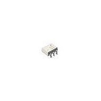
FOD420 Fairchild Semiconductor, FOD420 Datasheet - Page 4

FOD420
Manufacturer Part Number
FOD420
Description
Triac & SCR Output Optocouplers 600V RANDOM PHASE TRIAC
Manufacturer
Fairchild Semiconductor
Datasheet
1.FOD420.pdf
(12 pages)
Specifications of FOD420
Configuration
1
Maximum Input Current
30 mA
Maximum Operating Temperature
+ 100 C
Maximum Power Dissipation
500 mW
Maximum Reverse Diode Voltage
6 V
Maximum Turn-on Time
60 us
Minimum Operating Temperature
- 55 C
Output Type
AC
Package / Case
PDIP Black
Typical Input Voltage
1.28 V
Zero-crossing Circuit
No
Output Device
Triac
Isolation Voltage
5000 Vrms
Peak Output Voltage (vdrm)
600 V
Maximum Input Voltage
1.5 V
Maximum Output Voltage
420 VAC
Minimum Trigger Current
0.75 mA (Typ)
Number Of Elements
1
Forward Voltage
1.5V
Repetitive Peak Off-state Volt
600V
Operating Temp Range
-55C to 100C
Package Type
PDIP-B
Reverse Breakdown Voltage
6V
Mounting
Through Hole
Pin Count
6
Zero Crossing Circuit
No
Operating Temperature Classification
Industrial
Forward Current
30mA
Power Dissipation
500mW
Lead Free Status / RoHS Status
Lead free / RoHS Compliant
Available stocks
Company
Part Number
Manufacturer
Quantity
Price
Company:
Part Number:
FOD420SD
Manufacturer:
FSC
Quantity:
1 200
©2004 Fairchild Semiconductor Corporation
FOD420, FOD4208, FOD4216, FOD4218 Rev. 1.4.0
Notes:
2. Test voltage must be applied within dv/dt rating.
3. All devices are guaranteed to trigger at an I
4. This is static dv/dt. See Figure 11 for test circuit. Commutating dv/dt is a function of the load-driving thyristor(s) only.
5. Isolation voltage, V
Typical Application
Typical circuit for use when hot line switching is required.
In this circuit the “hot” side of the line is switched and the
load connected to the cold or neutral side. The load may
be connected to either the neutral or hot line.
I
max I
and Pins 4, 5 and 6 are common.
F
lies between max I
F
V
(30mA).
CC
* For highly inductive loads (power factor < 0.5), change this value to 360 ohms.
ISO
R
FT
in
, is an internal device dielectric breakdown rating. For this test, Pins 1, 2 and 3 are common,
(2mA for FOD420 and FOD4208 and 1.3mA for FOD4216 and FOD4218 and the absolute
1
2
3
Figure 1. Hot-Line Switching Application Circuit
FOD4208
FOD4216
FOD4218
FOD420
F
value less than or equal to max I
330
6
5
4
4
360
R
part, 2mA for FOD420 and FOD4208, 1.3mA for
FOD4216 and FOD4218. The 39
capacitor are for snubbing of the triac and may or may
not be necessary depending upon the particular triac
and load use.
in
is calculated so that I
FKPF12N80
FT
. Therefore, recommended operating
F
39*
0.01 F
is equal to the rated I
LOAD
resistor and 0.01µF
HOT
NEUTRAL
240 VAC
www.fairchildsemi.com
FT
of the


