NTLUD3191PZTBG ON Semiconductor, NTLUD3191PZTBG Datasheet
NTLUD3191PZTBG
Specifications of NTLUD3191PZTBG


Related parts for NTLUD3191PZTBG

NTLUD3191PZTBG Summary of contents
Page 1
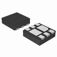
NTLUD3191PZ Power MOSFET −20 V, −1.8 A, mCoolt Dual P−Channel, ESD, 1.6x1.6x0.55 mm UDFN Package Features • UDFN Package with Exposed Drain Pads for Excellent Thermal Conduction • Low Profile UDFN 1.6 x 1.6 x 0.55 mm for Board Space ...
Page 2
THERMAL RESISTANCE RATINGS Junction-to-Ambient – Steady State (Note 3) Junction-to-Ambient – t ≤ (Note 3) Junction-to-Ambient – Steady State min Pad (Note 4) ELECTRICAL CHARACTERISTICS (T Parameter OFF CHARACTERISTICS Drain−to−Source Breakdown Voltage Drain−to−Source Breakdown Voltage Temperature Coefficient Zero ...
Page 3
V = −4 25° −V , DRAIN−TO−SOURCE VOLTAGE (V) DS Figure 1. On−Region Characteristics 1.0 0.9 0.8 0.7 0.6 0.5 ...
Page 4
C iss 175 150 125 100 oss 25 C rss −V , DRAIN−TO−SOURCE VOLTAGE (V) DS Figure 7. Capacitance Variation 100 V = −4 −10 ...
Page 5
... DEVICE ORDERING INFORMATION Device NTLUD3191PZTAG NTLUD3191PZTBG †For information on tape and reel specifications, including part orientation and tape sizes, please refer to our Tape and Reel Packaging Specifications Brochure, BRD8011/D. TYPICAL CHARACTERISTICS = − 25° LIMIT DS(on) THERMAL LIMIT ...
Page 6
... NOTE 3 0.05 C 0.50 PITCH *For additional information on our Pb−Free strategy and soldering details, please download the ON Semiconductor Soldering and Mounting Techniques Reference Manual, SOLDERRM/D. N. American Technical Support: 800−282−9855 Toll Free USA/Canada Europe, Middle East and Africa Technical Support: Phone: 421 33 790 2910 Japan Customer Focus Center Phone: 81− ...