DLP-RFID-UHF1B DLP Design Inc, DLP-RFID-UHF1B Datasheet - Page 4
DLP-RFID-UHF1B
Manufacturer Part Number
DLP-RFID-UHF1B
Description
RFID READER/WRITER USB INTERFACE
Manufacturer
DLP Design Inc
Datasheet
1.DLP-RFID-UHF1B.pdf
(6 pages)
Specifications of DLP-RFID-UHF1B
Rf Type
Read / Write
Frequency
900MHz
Features
ISO 18000-6 a/b/c
Package / Case
Module
Operating Current
320 mA
Output Power
18 dBm
Product
RFID Kits
Wireless Frequency
902.6 MHz to 927.4 MHz
Interface Type
USB
Dimensions
21.1 mm x 58.4 mm x 82.6 mm
Antenna
Reverse Polarity SMA
Operating Temperature Range
0 C to + 70 C
Lead Free Status / RoHS Status
Lead free / RoHS Compliant
Lead Free Status / RoHS Status
Lead free / RoHS Compliant, Lead free / RoHS Compliant
Other names
813-1029
Available stocks
Company
Part Number
Manufacturer
Quantity
Price
Company:

Part Number:
DLP-RFID-UHF1B
Manufacturer:
DLP Design Inc
Quantity:
135


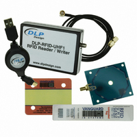
6.2 EXTERNAL ANTENNAS
The DLP-RFID-UHF1B is approved for use with selected external antennas. Connection is
made via reverse-polarity SMA connectors.
A magnetic loop antenna is provided with each DLP-RFID-UHF1B reader purchased from
DLP Design as shown below:
This antenna is well suited for reading the near-field loop incorporated into many Gen-2 tags.
This antenna requires a coax cable with a reverse-polarity SMA connector at one end for
connection to the DLP-RFID-UHF1B reader. A 3-foot coax cable is provided with each
DLP-RFID-UHF1B reader purchased from DLP Design.
6.3 FCC/IC REQUIREMENTS FOR MODULAR APPROVAL
Any changes or modifications to the DLP-RFID-UHF1B’s printed circuit board or magnetic loop
antenna could void the user’s authority to operate the equipment.
6.4 WARNINGS
Operation is subject to the following two conditions: (1) This device may not cause harmful
interference, and (2) this device must accept any interference received, including interference
that may cause undesirable operation.
This device is intended for use under the following conditions:
1. The transmitter module may not be co-located with any other transmitter or antenna; and,
2. The module has been approved using the FCC’s “unlicensed modular transmitter approval”
method. Only loop antennas that do not exhibit a directional gain greater than that of the
antenna provided with the device may be used.
As long as these two conditions are met, further transmitter testing will not be required.
However, the OEM integrator is still responsible for testing their end product for any additional
compliance measures necessitated by the installation of this module (i.e. digital device
emissions, PC peripheral requirements, etc.).
© DLP Design, Inc.
Rev 1.0 (November 2009)
4
Related parts for DLP-RFID-UHF1B
Image
Part Number
Description
Manufacturer
Datasheet
Request
R

Part Number:
Description:
RFID READER 8-CH
Manufacturer:
DLP Design Inc
Datasheet:

Part Number:
Description:
ANTENNA ROUND WITH COAX
Manufacturer:
DLP Design Inc
Datasheet:

Part Number:
Description:
RFID READER/WRITER SNGL-CH OEM
Manufacturer:
DLP Design Inc
Datasheet:

Part Number:
Description:
RFID Modules & Development Tools RFID Reader (Retail Box Version)
Manufacturer:
DLP Design Inc
Datasheet:

Part Number:
Description:
RFID TRANSPONDER TAGS HF 10-PACK
Manufacturer:
DLP Design Inc
Datasheet:

Part Number:
Description:
RFID READER/WRITER SNGL-CH
Manufacturer:
DLP Design Inc
Datasheet:

Part Number:
Description:
ANTENNA FERRITE
Manufacturer:
DLP Design Inc
Datasheet:

Part Number:
Description:
COAX WITH RPSMA CONNECTOR
Manufacturer:
DLP Design Inc
Datasheet:

Part Number:
Description:
RF Development Tools DLP-RFS1231 development kit
Manufacturer:
DLP Design
Datasheet:

Part Number:
Description:
MODULE USB-MCU FT245RL W/16F877A
Manufacturer:
DLP Design Inc
Datasheet:

Part Number:
Description:
MODULE USB-TO-FPGA TRAINING TOOL
Manufacturer:
DLP Design Inc
Datasheet:

Part Number:
Description:
MODULE USB-MCU FT232R W/18F2410
Manufacturer:
DLP Design Inc
Datasheet:

Part Number:
Description:
MODULE USB-MCU FT245RL W/SX48
Manufacturer:
DLP Design Inc
Datasheet:

Part Number:
Description:
MODULE USB-MCU FT2232D W/16F877A
Manufacturer:
DLP Design Inc
Datasheet:

Part Number:
Description:
MODULE USB-TO-FPGA SPARTAN3
Manufacturer:
DLP Design Inc
Datasheet: