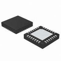
ATA5278-PKQI Atmel, ATA5278-PKQI Datasheet - Page 4

ATA5278-PKQI
Manufacturer Part Number
ATA5278-PKQI
Description
IC ANTENNA DVR STAND-ALONE 28QFN
Manufacturer
Atmel
Type
Stand Alone Antenna Driverr
Datasheet
1.ATA5278-PKQI.pdf
(34 pages)
Specifications of ATA5278-PKQI
Rf Type
TPM
Frequency
125kHz
Package / Case
28-VFQFN
Maximum Operating Temperature
+ 105 C
Mounting Style
SMD/SMT
Minimum Operating Temperature
- 40 C
Lead Free Status / RoHS Status
Lead free / RoHS Compliant
Features
-
Lead Free Status / Rohs Status
Lead free / RoHS Compliant
Other names
ATA5278-PKQITR
3. Functional Description
3.1
3.2
3.3
4
General Description
Operational States
Power-down Mode
ATA5278
The IC contains a half-bridge coil driver stage with a special driver voltage regulator and control
logic with diagnosis circuitry. It is controllable by a serial programming interface (SPI).
In combination with an LC antenna circuitry, the IC generates an electromagnetic LF field. The
carrier frequency for the antenna is generated by the oscillator and a pre-scaler logic.
The LF field can be modulated to transmit data to a suitable receiver. Two modulation modes
are available: Amplitude Shift Keying (ASK) and 180° Phase Shift Keying (PSK). The transmis-
sion data has to be stored in the internal data buffer.
The IC consists of two main functional blocks:
A boost converter is used to supply the driver half-bridge with a high voltage and a regulated
current even if the battery voltage is low. The antenna current is programmable in 16 steps to
support a transmission with various field strengths.
The driver circuitry is protected against short-circuits and overload.
After power-on-reset, the ATA5278 is in power-down mode. To achieve minimum power con-
sumption, only the internal 5-V supply and the control registers are active. The IC can only be
activated by the external control unit via the serial interface (i.e., the chip select line is enabled).
Once activated, the chip keeps the oscillator active and waits for commands on the serial bus.
This state can be described as standby mode. Only upon an external reset or on command fol-
lowed by disabling the chip select line, the power-down mode is re-invoked.
The modulator stage, together with the antenna driver and the power supply, is activated as
soon as LF data is written into the buffer and remains in this state until all data has been sent, a
stop command has been given via the SPI or a fault occurred. The data modulation is running
independently of the SPI activity and can be monitored with the MODACTIVE pin.
The ATA5278 should be kept in power-down mode as long as the LF channel is not used,
because not only is the current consumption minimal, but the internal logic is also reset. The
antenna driver stage is in high impedance mode. To power-up the chip, the chip-select line
(S_CS) has to be activated for an appropriate time. The SPI then starts the internal oscillator
which is necessary for proper operation. Only after a certain oscillation build-up time, is full func-
tionality available. The microcontroller can check out the state of the IC with two state bits
automatically returned by any SPI command.
• The SPI with the data buffer, the control registers and the oscillator
• The driver stage with its control logic and the power supply stage
4832D–RKE–12/07


